![[Compaq]](../../images/compaq.gif)
![[Go to the documentation home page]](../../images/buttons/bn_site_home.gif)
![[How to order documentation]](../../images/buttons/bn_order_docs.gif)
![[Help on this site]](../../images/buttons/bn_site_help.gif)
![[How to contact us]](../../images/buttons/bn_comments.gif)
![[OpenVMS documentation]](../../images/ovmsdoc_sec_head.gif)
| Document revision date: 19 July 1999 | |
![[Compaq]](../../images/compaq.gif) |
![[Go to the documentation home page]](../../images/buttons/bn_site_home.gif)
![[How to order documentation]](../../images/buttons/bn_order_docs.gif)
![[Help on this site]](../../images/buttons/bn_site_help.gif)
![[How to contact us]](../../images/buttons/bn_comments.gif)
|
![[OpenVMS documentation]](../../images/ovmsdoc_sec_head.gif)
|
|
| Previous | Contents | Index |
The following instructions are described in this section.
| Description and Opcode | Number of Instructions | |
|---|---|---|
| 1. |
Bit Clear PSW
BICPSW mask.rw |
1 |
| 2. |
Bit Set PSW
BISPSW mask.rw |
1 |
| 3. |
Breakpoint Fault
BPT {-(KSP).w*} |
1 |
| 4. |
Halt
HALT {-(KSP).w*} |
1 |
| 5. |
Index
INDEX subscript.rl, low.rl, high.rl, size.rl, indexin.rl, indexout.wl |
1 |
| 6. |
Move from PSL
MOVPSL dst.wl |
1 |
| 7. |
No Operation
NOP |
1 |
| 8. |
Pop Registers
POPR mask.rw, {(SP)+.r*} |
1 |
| 9. |
Push Registers
PUSHR mask.rw, {-(SP).w*} |
1 |
| 10. |
Extended Function Call
XFC {unspecified operands} |
1 |
Bit Clear PSW
opcode mask.rw
| N|| <--- N AND {NOT mask<3>}; | |
| Z|| <--- Z AND {NOT mask<2>}; | |
| V|| <--- V AND {NOT mask<1>}; | |
| C|| <--- C AND {NOT mask<0>}; |
| B9 | BICPSW | Bit Clear PSW |
The result of the logical AND on processor status word (PSW) and the one's complement of the mask operand replaces PSW.
A reserved operand fault occurs if mask<15:8> is not zero. On a reserved operand fault, the PSW is not affected.
Bit Set PSW
opcode mask.rw
| N|| <--- N OR mask<3>; | |
| Z|| <--- Z OR mask<2>; | |
| V|| <--- V OR mask<1>; | |
| C|| <--- C OR mask<0>; |
| B8 | BISPSW | Bit Set PSW |
The result of the logical OR on processor status word (PSW) and the mask operand replaces PSW.
A reserved operand fault occurs if mask<15:8> is not zero. On a reserved operand fault, the PSW is not affected.
Breakpoint Fault
opcode
| N|| <--- 0; ! Condition codes cleared after BPT fault | |
| Z|| <--- 0; | |
| V|| <--- 0; | |
| C|| <--- 0; |
| 03 | BPT | Breakpoint Fault |
To understand the operation of this instruction, refer to Appendix E. This instruction, together with the T-bit, is used to implement debugging facilities.
Halt
opcode
| N|| <--- 0; ! If privileged instruction fault, | |
| Z|| <--- 0; ! condition codes are cleared after | |
| V|| <--- 0; ! the fault. PSL saved on stack | |
| C|| <--- 0; ! contains condition codes prior to HALT. | |
| N|| <--- N; ! If processor halt | |
| Z|| <--- Z; | |
| V|| <--- V; | |
| C|| <--- C; |
| 00 | HALT | Halt |
If the process is running in kernel mode, the processor is halted. Otherwise, a privileged instruction fault occurs. For information about privileged instruction faults, refer to Appendix E.
This opcode is zero to trap many branches to data.
Compute Index
opcode subscript.rl, low.rl, high.rl, size.rl, indexin.rl,
indexout.wl
| N|| <--- indexout LSS 0; | |
| Z|| <--- indexout EQL 0; | |
| V|| <--- 0; | |
| C|| <--- 0; |
| 0A | INDEX | index |
The indexin operand is added to the subscript operand and the sum multiplied by the size operand. The indexout operand is replaced by the result. If the subscript operand is less than the low operand or greater than the high operand, a subscript range trap is taken.
COBOL:

01  A-ARRAY.
    02  A PIC X(10) OCCURS 15 TIMES.

01  B PIC X(10).
    MOVE A(I) TO B.
|
MACRO: INDEX I, #1, #15, #10, #0, R0 MOVC3 #10, A-10[R0], B. |
PL/I: DCL A(-3:10) BIT (5); A(I) = 1; |
MACRO: INDEX I, #-3, #10, #5, #3, R0 INSV #1, R0, #5, A ; Assumes A is byte aligned |
FORTRAN: INTEGER*4 A(L1:U1, L2:U2), I, J A(I,J) = 1 |
MACRO:

INDEX J, #L2, #U2, #M1, #0, R0; M1=U1-L1+1
INDEX I, #L1, #U1, #1, R0, R0;
MOVL     #1, A-a[R0]; a = {{L2*M1} + L1} *4
|
Move from PSL
opcode dst.wl
| N|| <--- N; | |
| Z|| <--- Z; | |
| V|| <--- V; | |
| C|| <--- C; |
| DC | MOVPSL | Move from PSL |
The destination operand is replaced by processor status longword (PSL).
No Operation
opcode
| N|| <--- N; | |
| Z|| <--- Z; | |
| V|| <--- V; | |
| C|| <--- C; |
| 01 | NOP | No Operation |
No operation is performed. Because the time delay caused by a NOP instruction is dependent on processor type, Digital recommends that you do not use NOP as a means of delaying program execution. When you must have a program wait for a specified period, you should use a macro, such as the TIMEDWAIT macro, or code sequence that is not dependent on the processor's internal speed.
Pop Registers
opcode mask.rw
| N|| <--- N; | |
| Z|| <--- Z; | |
| V|| <--- V; | |
| C|| <--- C; |
| BA | POPR | Pop Registers |
The contents of registers whose numbers correspond to set bits in the mask operand are replaced by longwords popped from the stack. R[n] is replaced if mask<n> is set. The mask is scanned from bit 0 to bit 14. Bit 15 is ignored.
Push Registers
opcode mask.rw
| N|| <--- N; | |
| Z|| <--- Z; | |
| V|| <--- V; | |
| C|| <--- C; |
| BB | PUSHR | Push Registers |
The contents of registers whose numbers correspond to set bits in the mask operand are pushed on the stack as longwords. R[n] is pushed if mask<n> is set. The mask is scanned from bit 14 to bit 0. Bit 15 is ignored.
The order of pushing is specified so that the contents of higher-numbered registers are stored at higher memory addresses. An example of a result of this would be a double-floating datum stored in adjacent registers being stored by PUSHR in memory in the correct order.
Extended Function Call
opcode
| N|| <--- 0; | |
| Z|| <--- 0; | |
| V|| <--- 0; | |
| C|| <--- 0; |
| FC | XFC | Extended Function Call |
To understand the operation of this instruction, refer to Appendix E and the VAX Architecture Reference Manual. This instruction provides for customer-defined extensions to the instruction set.
9.2.7 Queue Instructions
A queue is a circular, doubly linked list. A queue entry is specified
by its address. Each queue entry is linked to the next by a pair of
longwords. The first longword is the forward link; it specifies the
location of the succeeding entry. The second longword is the backward
link; it specifies the location of the preceding entry. Because a queue
contains redundant links, it is possible to create ill-formed queues.
The VAX instructions produce UNPREDICTABLE results when used on
ill-formed queues.
A queue is classified by the type of link that it uses. The VAX
supports two distinct types of links: absolute and self-relative.
9.2.7.1 Absolute Queues
Absolute queues use absolute addresses as links. Queue entries are linked by a pair of longwords. The first (lowest-addressed) longword is the forward link; it is the address of the succeeding queue entry. The second (highest-addressed) longword is the backward link; it is the address of the preceding queue entry.
A queue is specified by a queue header, which is identical to a pair of queue linkage longwords. The forward link of the header is the address of the entry called the head of the queue. The backward link of the header is the address of the entry termed the tail of the queue. The forward link of the tail points to the header.
Two general operations can be performed on queues: insertion of entries and removal of entries. Generally, entries can be inserted or removed only at the head or tail of a queue. (Under certain restrictions they can be inserted or removed elsewhere; this is discussed later.)
The following text contains examples of queue operations. An empty queue is specified by its header at address H.

If an entry at address B is inserted into an empty queue (at either the head or the tail), the queue appears as follows:

If an entry at address A is inserted at the head of the queue, the queue appears as follows:
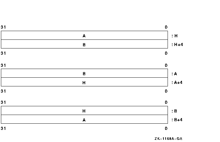
Finally, if an entry at address C is inserted at the tail, the queue appears as follows:
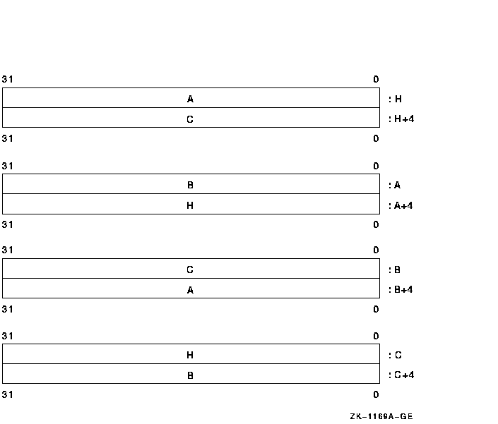
Following the preceding steps in reverse order gives the effect of removal at the tail and removal at the head.
If more than one process can perform operations on a queue simultaneously, insertions and removals should only be done at the head or tail of the queue. If only one process (or one process at a time) can perform operations on a queue, insertions and removals can be made at other than the head or tail of the queue. In the preceding example with the queue containing entries A, B, and C, the entry at address B can be removed, giving the following:
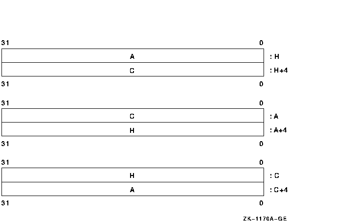
The reason for this restriction is that operations at the head or tail are always valid because the queue header is always present. Operations elsewhere in the queue depend on specific entries being present and may become invalid if another process is simultaneously performing operations on the queue.
Two instructions are provided for manipulating absolute queues: INSQUE
and REMQUE. INSQUE inserts an entry specified by an entry operand into
the queue following the entry specified by the predecessor operand.
REMQUE removes the entry specified by the entry operand. Queue entries
can be on arbitrary byte boundaries. Both INSQUE and REMQUE are
implemented as noninterruptible instructions.
9.2.7.2 Self-Relative Queues
Self-relative queues use displacements from queue entries as links. Queue entries are linked by a pair of longwords. The first (lowest addressed) longword is the forward link; it is the displacement of the succeeding queue entry from the present entry. The second (highest-addressed) longword is the backward link; it is the displacement of the preceding queue entry from the present entry.
A queue is specified by a queue header, which also consists of two longword links. The forward link of the header is the address of the entry called the head of the queue. The backward link of the header is the address of the entry called the tail of the queue. The forward link of the tail points to the header.
The following text contains examples of queue operations. An empty queue is specified by its header at address H. Because the queue is empty, the self-relative links must be zero, as shown.

If an entry at address B is inserted into an empty queue (at either the head or tail), the queue appears as follows:
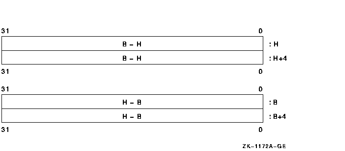
If an entry at address A is inserted at the head of the queue, the queue appears as follows:
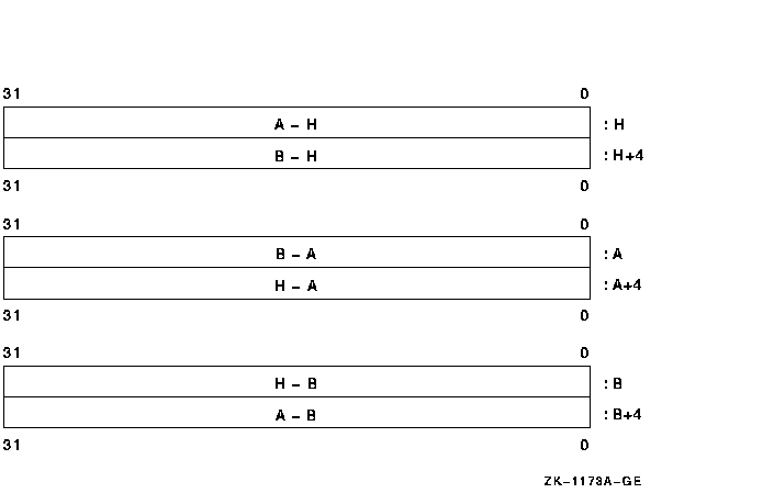
Finally, if an entry at address C is inserted at the tail, the queue appears as follows:
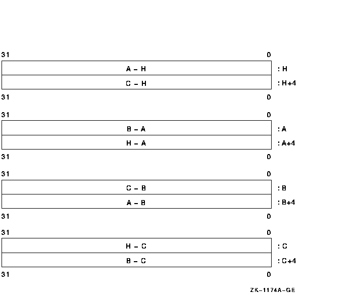
Following the previous steps in reverse order gives the effect of removal at the tail and at the head.
The following four instructions manipulate self-relative queues:
These operations are interlocked to allow cooperating processes in a multiprocessor system to access a shared list without additional synchronization. Queue entries must be quadword aligned. A hardware-supported interlocked memory access mechanism is used to read the queue header. Bit 0 of the queue header is used as a secondary interlock; it is set when the queue is being accessed.
If an interlocked queue instruction encounters the secondary interlock set, then, if no exception conditions exist, it terminates after setting the condition codes to indicate failure to gain access to the queue. If the secondary interlock bit is not set, then the interlocked queue instruction sets the secondary interlock bit during instruction execution and clears the secondary interlock bit at instruction completion. In this way, other interlocked queue instructions are prevented from operating on the same queue.
If an interlocked queue instruction encounters both the secondary interlock set and an exception condition resulting from instruction execution, then it is UNPREDICTABLE whether the exception occurs or the instruction terminates after setting the condition codes.
| Previous | Next | Contents | Index |
![[Go to the documentation home page]](../../images/buttons/bn_site_home.gif)
![[How to order documentation]](../../images/buttons/bn_order_docs.gif)
![[Help on this site]](../../images/buttons/bn_site_help.gif)
![[How to contact us]](../../images/buttons/bn_comments.gif)
|
| privacy and legal statement | ||
| 4515PRO_021.HTML | ||