![[Compaq]](../../images/compaq.gif)
![[Go to the documentation home page]](../../images/buttons/bn_site_home.gif)
![[How to order documentation]](../../images/buttons/bn_order_docs.gif)
![[Help on this site]](../../images/buttons/bn_site_help.gif)
![[How to contact us]](../../images/buttons/bn_comments.gif)
![[OpenVMS documentation]](../../images/ovmsdoc_sec_head.gif)
| Document revision date: 19 July 1999 | |
![[Compaq]](../../images/compaq.gif) |
![[Go to the documentation home page]](../../images/buttons/bn_site_home.gif)
![[How to order documentation]](../../images/buttons/bn_order_docs.gif)
![[Help on this site]](../../images/buttons/bn_site_help.gif)
![[How to contact us]](../../images/buttons/bn_comments.gif)
|
![[OpenVMS documentation]](../../images/ovmsdoc_sec_head.gif)
|
|
| Previous | Contents | Index |
Case
opcode selector.rx, base.rx, limit.rx,
displ[0].bw,
...,
displ[limit].bw
| N|| <--- tmp LSS limit; | |
| Z|| <--- tmp EQL limit; | |
| V|| <--- 0; | |
| C|| <--- tmp LSSU limit; |
| 8F | CASEB | Case Byte |
| AF | CASEW | Case Word |
| CF | CASEL | Case Long |
The base operand is subtracted from the selector operand, and the result replaces a temporary operand. The temporary operand is compared with the limit operand; if it is less than or equal unsigned, a branch displacement selected by the temporary value is added to the program counter (PC), and the PC is replaced by the result. Otherwise, twice the sum of the limit operand and 1 is added to the PC, and the PC is replaced by the result. This operation causes the PC to be moved past the array of branch displacements. Regardless of the branch taken, the condition codes are modified as a result of the comparison of the temporary operand with the limit operand.
In the following example, the CASEB instruction selects one of eight displacements immediately following the instruction. The example is for illustration only. An actual instruction would use run-time variables instead of the assembly-time static values shown. Also, in an actual instruction, the displacements selected by the CASEB instruction would be branches to various routines.
        .PSECT    CODE, PIC, SHR, WRT, EXE, LONG
TABIND: .WORD 4
        .ENTRY    START,^M<>
        CLRW      R4
        CLRW      R5
        MOVW      #0,R4
        MOVW      #7,R5
        CASEB     TABIND,R4,R5
TAB:    .WORD     1$-TAB
        .WORD     2$-TAB
        .WORD     3$-TAB
        .WORD     4$-TAB
        .WORD     5$-TAB
        .WORD     6$-TAB
        .WORD     7$-TAB
        BRB       9$
1$:     .ASCII    /AT 1/
2$:     .ASCII    /AT 2/
3$:     .ASCII    /AT 3/
4$:     .ASCII    /AT 4/
5$:     .ASCII    /AT 5/
6$:     .ASCII    /AT 6/
7$:     .ASCII    /AT 7/
8$:     .ASCII    /AT 8/
9$:     $EXIT_S
        .END START
|
The objective of the CASE instruction is to transfer control to one of many possible locations depending on the value of "selector," or TABIND, as shown in the example. These locations are labeled in the example from 1$: to 8$:.
In the example, the table contains eight branch displacements. In all cases, the limit operand (here shown as R5, which contains a 7) is one less than the number of displacements (8) in the table. The base operand (here shown as R4, which contains a zero) is the lowest permissible value for TABIND.
The CASE instruction subtracts base (contents of R4, a zero) from the value of TABIND to produce a zero-origin index into the table. The limit (contents of R5, a 7) is compared with this index to ensure that the table limit is not exceeded.
After operand evaluation, the program counter (PC) points to TAB:. The locations to which branching occurs are represented in the table as displacements. The displacement in the table selected by TABIND is added to the PC to form a destination address. The destination selected in the example is at location 5$:. In practical usage, this location would contain a branch to a specific routine.
Jump
opcode dst.ab
| N|| <--- N; | |
| Z|| <--- Z; | |
| V|| <--- V; | |
| C|| <--- C; |
| 17 | JMP | Jump |
The program counter (PC) is replaced by the destination operand.
Jump to Subroutine
opcode dst.ab
| N|| <--- N; | |
| Z|| <--- Z; | |
| V|| <--- V; | |
| C|| <--- C; |
| 16 | JSB | Jump to Subroutine |
The program counter (PC) is pushed onto the stack as a longword. The PC is replaced by the destination operand.
Because the operand specifier conventions cause the evaluation of the destination operand before saving the PC, you can use JSB for coroutine calls with the stack used for linkage. The form of this call is:
JSB @(SP)+ |
Return from Subroutine
opcode
| N|| <--- N; | |
| Z|| <--- Z; | |
| V|| <--- V; | |
| C|| <--- C; |
| 05 | RSB | Return from Subroutine |
The program counter (PC) is replaced by a longword popped from the stack.
Subtract One and Branch Greater Than or Equal
opcode index.ml, displ.bb
| N|| <--- index LSS 0; | |
| Z|| <--- index EQL 0; | |
| V|| <--- {integer overflow}; | |
| C|| <--- C; |
| F4 | SOBGEQ | Subtract One and Branch Greater Than or Equal |
One is subtracted from the index operand, and the index operand is replaced by the result. If the index operand is greater than or equal to zero, the sign-extended branch displacement is added to the program counter (PC), and the PC is replaced by the result.
Subtract One and Branch Greater Than
opcode index.ml, displ.bb
| N|| <--- index LSS 0; | |
| Z|| <--- index EQL 0; | |
| V|| <--- {integer overflow}; | |
| C|| <--- C; |
| F5 | SOBGTR | Subtract One and Branch Greater Than |
One is subtracted from the index operand, and the index operand is replaced by the result. If the index operand is greater than zero, the sign-extended branch displacement is added to the program counter (PC), and the PC is replaced by the result.
9.2.5 Procedure Call Instructions
The following three instructions implement a standard procedure calling
interface:
CALLG and CALLS call the procedure. The RETURN instruction returns from the procedure. Refer to the OpenVMS Programming Interfaces: Calling a System Routine for the procedure calling standard.
The CALLG instruction calls a procedure with the argument list in an arbitrary location.
The CALLS instruction calls a procedure with the argument list on the stack. Upon return after a CALLS instruction, this list is automatically removed from the stack. Both call instructions specify the address of the entry point of the procedure being called. The entry point is assumed to consist of a word called the entry mask followed by the procedure's instructions. The procedure terminates by executing a RET instruction.
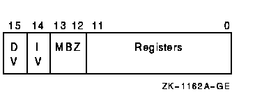
The entry mask specifies the register use and overflow enables of the subprocedure.

At the occurrence of one of the call instructions, the stack is aligned to a longword boundary, and the trap enables in the processor status longword (PSW) are set to a known state to ensure consistent behavior of the called procedure. Integer overflow enable and decimal overflow enable are affected according to bits 14 and 15 of the entry mask, respectively. Floating underflow enable is cleared. Registers R11 to R0, specified by bits 11 to 0, respectively, are saved on the stack and are restored by the RET instruction. In addition, the program counter (PC), stack pointer (SP), frame pointer (FP), and argument pointer (AP) are always preserved by the CALL instructions and restored by the RET instruction.
All external procedure calls generated by standard Digital language processors and all intermodule calls to major VAX software subsystems comply with the procedure calling software standard (see the VAX Procedure Calling and Condition Handling Standard in the OpenVMS Programming Interfaces: Calling a System Routine). The procedure calling standard requires that all registers in the range R2 to R11 used in the procedure must appear in the mask. R0 and R1 are not preserved by any called procedure that complies with the procedure calling standard.
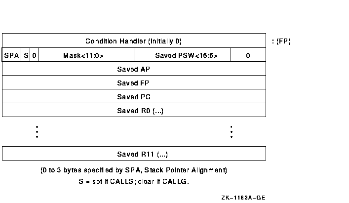
To preserve the state, the CALL instructions form a structure on the stack termed a call frame or stack frame. The call frame contains the saved registers, the saved PSW, the register save mask, and several control bits. The frame also includes a longword that the CALL instructions clear. The system uses this longword to implement the OpenVMS condition handling facility (see the VAX Procedure Calling and Condition Handling Standard in the OpenVMS Programming Interfaces: Calling a System Routine). At the end of execution of the CALL instruction,the frame pointer (FP) contains the address of the stack frame. The RET instruction uses the contents of FP to find the stack frame and the restore state. The condition handling facility assumes that FP always points to the stack frame.
The stack frame has the following format:

Note that the saved condition codes and the saved trace enable (PSW<T>) are cleared.
The contents of the frame PSW<3:0> at the time RET is executed will become the condition codes resulting from the execution of the procedure. Similarly, the content of the frame PSW<4> at the time the RET is executed will become the PSW<T> bit.
The following instructions are described in this section.
| Description and Opcode | Number of Instructions | |
|---|---|---|
| 1. |
Call Procedure with General Argument List
CALLG arglist.ab, dst.ab, {-(SP).w*} |
1 |
| 2. |
Call Procedure with Stack Argument List
CALLS numarg.rl, dst.ab, {-(SP).w*} |
1 |
| 3. |
Return from Procedure
RET {(SP)+.r*} |
1 |
Call Procedure with General Argument List
opcode arglist.ab, dst.ab
| N|| <--- 0; | |
| Z|| <--- 0; | |
| V|| <--- 0; | |
| C|| <--- 0; |
| FA | CALLG | Call Procedure with General Argument List |
The stack pointer (SP) is saved in a temporary register. Bits 1:0 are replaced by zero, so that the stack is longword aligned. The procedure entry mask is scanned from bit 11 to bit 0, and the contents of registers whose numbers correspond to set bits in the mask are pushed on the stack as longwords. The program counter (PC), frame pointer (FP), and argument pointer (AP) are pushed on the stack as longwords. The condition codes are cleared. A longword containing the saved low 2 bits of the SP in bits 31:30, a zero in bits 29 and 28, the low 12 bits of the procedure entry mask in bits 27:16, and the processor status word (PSW) in bits 15:0 with T cleared are pushed on the stack. A longword zero is pushed on the stack. The FP is replaced by the SP. The AP is replaced by the arglist operand. The trap enables in the PSW are set to a known state. Integer overflow and decimal overflow are affected according to bits 14 and 15 of the entry mask, respectively; floating underflow is cleared. The T-bit is unaffected. The PC is replaced by the sum of destination operand plus 2, which transfers control to the called procedure at the byte beyond the entry mask.

Call Procedure with Stack Argument List
opcode numarg.rl, dst.ab
| N|| <--- 0; | |
| Z|| <--- 0; | |
| V|| <--- 0; | |
| C|| <--- 0; |
| FB | CALLS | Call Procedure with Stack Argument List |
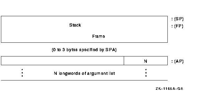
The numarg operand is pushed on the stack as a longword (byte 0 contains the number of arguments; Digital software uses the high-order 24 bits). The stack pointer (SP) is saved in a temporary register, and then bits 1:0 of the SP are replaced by zero so that the stack is longword aligned. The procedure entry mask is scanned from bit 11 to bit 0, and the contents of registers whose numbers correspond to set bits in the mask are pushed on the stack. The program counter (PC), frame pointer (FP), and argument pointer (AP) are pushed on the stack as longwords. The condition codes are cleared. A longword containing the saved low 2 bits of the SP in bits 31:30, a 1 in bit 29, a zero in bit 28, the low 12 bits of the procedure entry mask in bits 27:16, and the processor status word (PSW) in bits 15:0 with T cleared is pushed on the stack. A longword zero is pushed on the stack. The FP is replaced by the SP. The AP is set to the value of the stack pointer after the numarg operand was pushed on the stack. The trap enables in the PSW are set to a known state. Integer overflow and decimal overflow are affected according to bits 14 and 15 of the entry mask, respectively. Floating underflow is cleared. The T-Bit is unaffected.The PC is replaced by the sum of destination operand plus 2, which transfers control to the called procedure at the byte beyond the entry mask. The appearance of the stack after CALLS is executed is:

Return from Procedure
opcode
| N|| <--- tmp1<3>; | |
| Z|| <--- tmp1<2>; | |
| V|| <--- tmp1<1>; | |
| C|| <--- tmp1<0>; |
| 04 | RET | Return from Procedure |
The stack pointer (SP) is replaced by the frame pointer (FP) plus 4. A longword containing stack alignment bits in bits 31:30, a CALLS/CALLG flag in bit 29, the low 12 bits of the procedure entry mask in bits 27:16, and a saved processor status word (PSW) in bits 15:0 is popped from the stack and saved in a temporary. The program counter (PC), frame pointer (FP), and argument pointer (AP) are replaced by longwords popped from the stack. A register restore mask is formed from bits 27:16 of the temporary. Scanning from bit 0 to bit 11 of the restore mask, the contents of registers whose numbers are indicated by set bits in the mask are replaced by longwords popped from the stack. The SP is incremented by 31:30 of the temporary. The PSW is replaced by bits 15:0 of the temporary. If bit 29 in the temporary is 1 (indicating that the procedure was called by CALLS), a longword containing the number of arguments is popped from the stack. Four times the unsigned value of the low byte of this longword is added to the SP, and the SP is replaced by the result.
| Previous | Next | Contents | Index |
![[Go to the documentation home page]](../../images/buttons/bn_site_home.gif)
![[How to order documentation]](../../images/buttons/bn_order_docs.gif)
![[Help on this site]](../../images/buttons/bn_site_help.gif)
![[How to contact us]](../../images/buttons/bn_comments.gif)
|
| privacy and legal statement | ||
| 4515PRO_020.HTML | ||