![[Compaq]](../../images/compaq.gif)
![[Go to the documentation home page]](../../images/buttons/bn_site_home.gif)
![[How to order documentation]](../../images/buttons/bn_order_docs.gif)
![[Help on this site]](../../images/buttons/bn_site_help.gif)
![[How to contact us]](../../images/buttons/bn_comments.gif)
![[OpenVMS documentation]](../../images/ovmsdoc_sec_head.gif)
| Document revision date: 19 July 1999 | |
![[Compaq]](../../images/compaq.gif) |
![[Go to the documentation home page]](../../images/buttons/bn_site_home.gif)
![[How to order documentation]](../../images/buttons/bn_order_docs.gif)
![[Help on this site]](../../images/buttons/bn_site_help.gif)
![[How to contact us]](../../images/buttons/bn_comments.gif)
|
![[OpenVMS documentation]](../../images/ovmsdoc_sec_head.gif)
|
|
| Previous | Contents | Index |
The possible condition values that the called routine can return in a mailbox are listed under the Condition Values Returned in a Mailbox heading.
Routines such as SYS$SNDOPR that return condition values in a mailbox
send information to another process to perform a task. The receiving
process performs the action and returns the status of the task to the
mailbox of the sending process.
1.5.4 Condition Values Signaled
The possible condition values that the called routine can signal (instead of returning them in R0) are listed under the Condition Values Signaled heading.
Routines that signal condition values as a way of indicating the completion status do so because these routines are returning actual data as the value of the routine.
As mentioned, the signaling of condition values occurs whenever a routine generates an exception condition, regardless of how the routine returns its completion status under normal circumstances.
The OpenVMS Calling Standard defines the concepts and conventions used by common languages to invoke routines and pass data between them. This chapter briefly describes the following calling standard conventions:
Refer to the OpenVMS Calling Standard for more detail on calling conventions and
for standards defining argument data types, descriptor formats, and
procedures for condition handling and stack unwinding.
2.1 Hardware Registers
Registers in the hardware provide the necessary temporary storage for
computation within OpenVMS software procedures. The number of registers
available and their usage vary between the Alpha and VAX systems.
2.1.1 Register Usage for OpenVMS VAX
The calling standard defines several VAX registers and their use, as listed in Table 2-1.
| Register | Use |
|---|---|
| PC | Program counter |
| SP | Stack pointer |
| FP | Current stack frame pointer |
| AP | Argument pointer |
| R1 | Environment value (when necessary) |
| R0, R1 | Function return value registers |
By definition, any called routine can use registers R2 through R11 for
computation and the AP register as a temporary register.
2.1.2 Register Usage for OpenVMS Alpha
On Alpha systems, there are two groups of 64-bit wide, general-purpose Alpha hardware registers:
The first 32 general-purpose registers support integer processing; the
second 32 support floating-point operations.
2.1.2.1 Integer Registers
The calling standard defines the Alpha general-purpose integer registers and their use, as listed in Table 2-2.
| Register | Usage |
|---|---|
| R0 | Function value register. A standard call that returns a nonfloating-point function must return the function result in this register. The register can be modified by the called procedure without being saved and restored. |
| R1 | Conventional scratch register. In a standard call, this register can be modified by the called procedure without being saved and restored. |
| R2--15 | Conventional saved registers. If a standard-conforming procedure modifies one of these registers, the procedure must save and restore it. |
| R16--21 | Argument registers. Up to six nonfloating-point items of the argument list are passed in these registers and the registers can be modified by the called procedure without being saved and restored. |
| R22--24 | Conventional scratch registers. The registers can be modified by the called procedure without being saved and restored. |
| R25 | Argument information (AI) register. The register describes the argument list (see Section 2.4 for a detailed description) and can be modified by the called procedure without being saved and restored. |
| R26 | Return address (RA) register. The return address must be passed in this register and can be modified by the called procedure without being saved and restored. |
| R27 | Procedure value (PV) register. The procedure value of the procedure being called is passed in this register and can be modified by the called procedure without being saved and restored. |
| R28 | Volatile scratch register. The contents of this register are always unpredictable after any external transfer of control either to or from a procedure. |
| R29 | Frame pointer (FP). This register defines which procedure is the current procedure. |
| R30 | Stack pointer (SP). This register contains a pointer to the top (start) of the current operating stack. |
| R31 | ReadAsZero/Sink (RZ). Hardware defined: binary zero as a source operand, sink (no effect) as a result operand. |
2.1.2.2 Floating-Point Registers
The calling standard defines the Alpha floating-point registers and
their use, as listed in Table 2-3.
| Register | Usage |
|---|---|
| F0 | Floating-point function value register. In a standard call that returns a floating-point result in a register, this register is used to return the real part of the result. The register can be modified by the called procedure without being saved and restored. |
| F1 | Floating-point function value register. In a standard call that returns a complex floating-point result in registers, this register is used to return the imaginary part of the result. This register can be modified by the called procedure without being saved and restored. |
| F2--9 | Conventional saved registers. If a standard-conforming procedure modifies one of these registers, the procedure must save and restore it. |
| F10--15 | Conventional scratch registers. The registers can be modified by the called procedure without being saved and restored. |
| F16--21 | Argument registers. Up to six floating-point arguments can be passed by value in these registers. These registers can be modified by the called procedure without being saved and restored. |
| F22--30 | Conventional scratch registers. The registers can be modified by the called procedure without being saved and restored. |
| F31 | ReadAsZero/Sink. Hardware defined: binary zero as a source operand, sink (no effect) as a result operand. |
A stack is a last-in/first-out (LIFO) temporary storage area that the system allocates for every user process. The system keeps information about each routine call in the current image on the call stack. Then, each time you call a routine, the system creates a structure on the stack, defined as the stack frame.
Stack frames and call frames are synonymous. A call frame for each
procedure has a specified format containing pointers and control
information necessary in the transfer of control between procedures of
a call chain. Stack frames (call frames) of standard calling procedures
differ between Alpha and VAX systems.
2.2.1 Stack Procedure Usage for VAX
Figure 2-1 shows the format of the stack frame created for the called procedure by the CALLG or CALLS instruction. The stack frame (pointed to by SP) is in the context of the current procedure, and call frames (pointed to by FP) are the preserved stack frames of other active procedures in the call chain. The stack frame (call frame) for each procedure in the chain contains the following:
Figure 2-1 Call Frame Generated by CALLG and CALLS Instructions
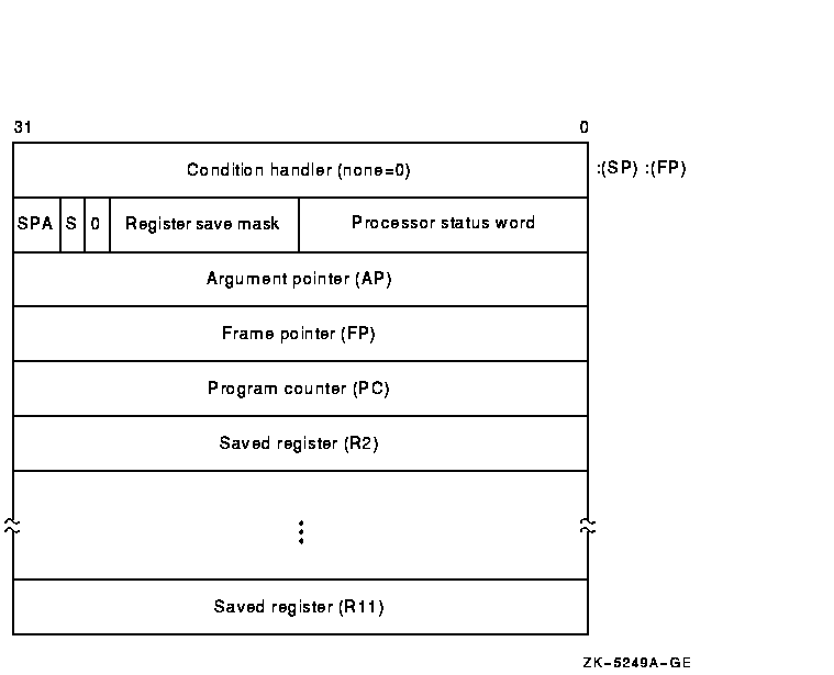
The contents of the stack located at addresses following the call frame belong to the calling program; they should not be read or written by the called procedure, except as specified in the argument list. The contents of the stack located at addresses lower than the call frame (at FP) belong to interrupt and exception routines; they are modified continually and unpredictably.
The called procedure allocates local storage by subtracting the
required number of bytes from the stack provided on entry. This local
storage is freed automatically by the RET instruction.
2.2.1.1 Calling Sequence
At the option of the calling procedure, the called procedure is invoked using the CALLG or CALLS instruction, as follows:
     CALLG    arglst, procedure
     CALLS    argcnt, procedure
|
CALLS pushes the argument count argcnt onto the stack as a longword and sets the argument pointer, AP, to the top of the stack. The complete sequence using CALLS follows:
     push     argn
     .
     .
     .
     push     arg1
     CALLS    #n, procedure
|
If the called procedure returns control to the calling procedure, control must return to the instruction immediately following the CALLG or CALLS instruction. Skip returns and GOTO returns are allowed only during stack unwind operations.
The called procedure returns control to the calling procedure by executing the return instruction (RET).
Note that when a routine completes execution, the system uses the FP in
the call frame of the current procedure to locate the frame of the
previous procedure. The system then removes the stack frame of the
current procedure from the stack.
2.2.2 Stack Procedure Usage for Alpha
On Alpha systems, when a standard procedure is called, the language compiler creates a stack frame for that procedure. The stack format of a stack frame procedure consists of a fixed part (the size of which is known at compile time) and an optional variable part. There are two basic types of stack frames:
Figure 2-2 illustrates the format of the stack frame for a procedure with a fixed amount of stack. The SP register is the stack base pointer for a fixed-size stack. In this case, R29 (FP) typically contains the address of the procedure descriptor for the current procedure.
The optional parts of the stack frame are created only as required by the particular procedure. As shown in Figure 2-2, the field names within brackets are optional fields. The fixed temporary locations are optional sections of any stack frame that contain language-specific locations required by the procedure context of some high-level languages.
The register save area is a set of consecutive quadwords in which registers that are saved and restored by the current procedure are stored. The register save area (RSA) begins at the location pointed to by the RSA offset. The contents of the return address register (R26) are always saved in the first register field (SAVED_RETURN) of the register save area.
Use of the arguments passed in memory appending the end of the frame is described in Section 2.4. For more detail concerning the fixed-size stack frame, see the OpenVMS Calling Standard.
Figure 2-2 Fixed-Size Stack Frame Format
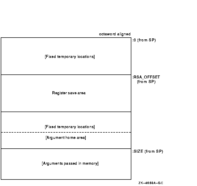
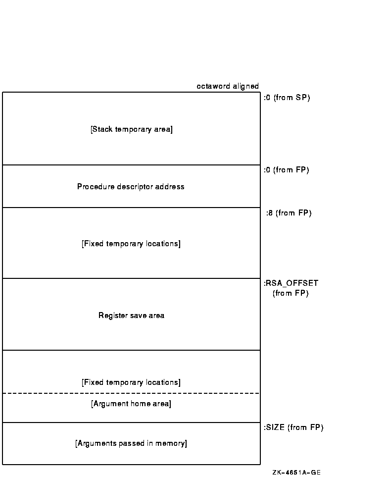
Figure 2-3 illustrates the format of the stack frame for procedures with a varying amount of stack when PDSC$V_BASE_REG_IS_FP is 1. In this case, R29 (FP) contains the address that points to the base of the stack frame on the stack. This frame-base quadword location contains the address of the current procedure's descriptor.
The optional parts of the stack frame are created as required by the particular procedure. As shown in Figure 2-3, field names within brackets are optional fields. The fixed temporary locations are optional sections of any stack frame that contain language-specific locations required by the procedure context of some high-level languages.
A compiler can use the stack temporary area pointed to by the SP base register for fixed local variables, such as constant-sized data items and program state, as well as for dynamically sized local variables. The stack temporary area may also be used for dynamically sized items with a limited lifetime, for example, a dynamically sized function result or string concatenation that cannot be directly stored in a target variable. When a procedure uses this area, the compiler must keep track of its base and reset SP to the base to reclaim storage used by temporaries.
The register save area is a set of consecutive quadwords in which registers saved and restored by the current procedure are stored. The register save area (RSA) begins at the location pointed to by the offset PDSC$W_RSA_OFFSET. The contents of the return address register (R26) is always saved in the first register field (SAVED_RETURN) of the register save area.
Use of the arguments passed in memory appending the end of the frame is described in Section 2.4. For more detail concerning the variable-size stack frame, see the OpenVMS Calling Standard.
Figure 2-3 Variable-Size Stack Frame Format
A procedure value is an address value that represents a procedure.
On Alpha systems, the procedure value in R27 is the address of the procedure descriptor that describes that procedure. So any OpenVMS Alpha procedure can be invoked by calling the stored address at offset 8 from the procedure descriptor (PDSC) starting address (procedure value).
On VAX systems, the procedure value is the address of the procedure
entry mask that begins the actual code sequence of the procedure.
2.4 Argument List
The calling standard defines a data structure called the argument list. An argument list is a sequence of locations in memory that represents a routine parameter list and possibly includes a function value. You use an argument list to pass information to a routine and receive results.
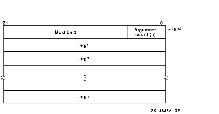
On VAX systems, the first longword in an argument list (see Figure 2-4) stores the number of arguments (the argument count, n) as an unsigned integer value. The maximum argument count is 255. The remaining 24 bits of the first longword are reserved for use by Digital and must be 0.
Both integer and floating-point values can be an argument passed in the argument list. Note that a 64-bit floating-point argument counts as 2 longword arguments in the list.
Figure 2-4 Structure of a VAX Argument List
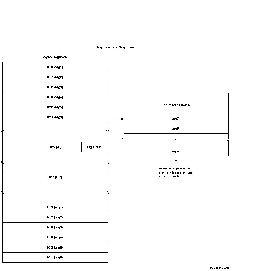
On Alpha systems, arguments are quadwords, and the calling program passes arguments in an argument item sequence. Each quadword in the sequence specifies a single argument. The argument item sequence is formed using R16--21 or F16--21 (a register for each argument). The argument item sequence can have a mix of integer and floating-point items that use both register types but must not repeat the same number. For example, an argument list might use R16, R17, F18, and R19. If there are more than six arguments, the argument items overflow to the end of the stack, as shown in Figure 2-5.
Figure 2-5 Alpha Argument List Format
The calling procedure must pass to the called procedure information about the argument list. For high-level languages, this is performed by the language processor. In the argument information (AI) register (R25), the quadword format is the structure shown in Figure 2-6. The AI register contains the argument count in the first byte. Table 2-4 describes the argument information fields in detail.
Figure 2-6 Argument Information (AI) Register (R25) Format

| Field Name | Contents | ||||||||||||||||||||||||
|---|---|---|---|---|---|---|---|---|---|---|---|---|---|---|---|---|---|---|---|---|---|---|---|---|---|
| AI$B_ARG_COUNT | Unsigned byte <7:0> that specifies the number of 64-bit argument items in the argument list (known as the argument count). | ||||||||||||||||||||||||
| AI$V_ARG_REG_INFO |
An 18-bit vector field <25:8> divided into 6 groups of 3 bits
that correspond to the 6 arguments passed in registers. These groups
describe how each of the first six arguments are passed in registers
with the first group <10:8> describing the first argument. The
encoding for each group for the argument register usage follows:
|
||||||||||||||||||||||||
| Bits <63:26> | Reserved and must be 0. |
Each high-level language supported by OpenVMS provides a mechanism for passing arguments to a procedure. The specifics of the mechanism and the terminology used, however, vary from one language to another. For specific information, refer to the appropriate high-level language user's guide.
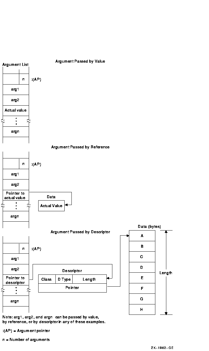
OpenVMS system routines are external procedures that accept arguments. The argument list contains the parameters that are passed to the routine. Depending on the passing mechanisms for these parameters, the forms of the arguments contained in the argument list vary. As shown in Figures 2-7 and 2-8, argument entries labeled arg1 through argn are the actual parameters, which can be any of the following addresses or value:
Figure 2-7 Alpha Procedure Argument-Passing Mechanisms
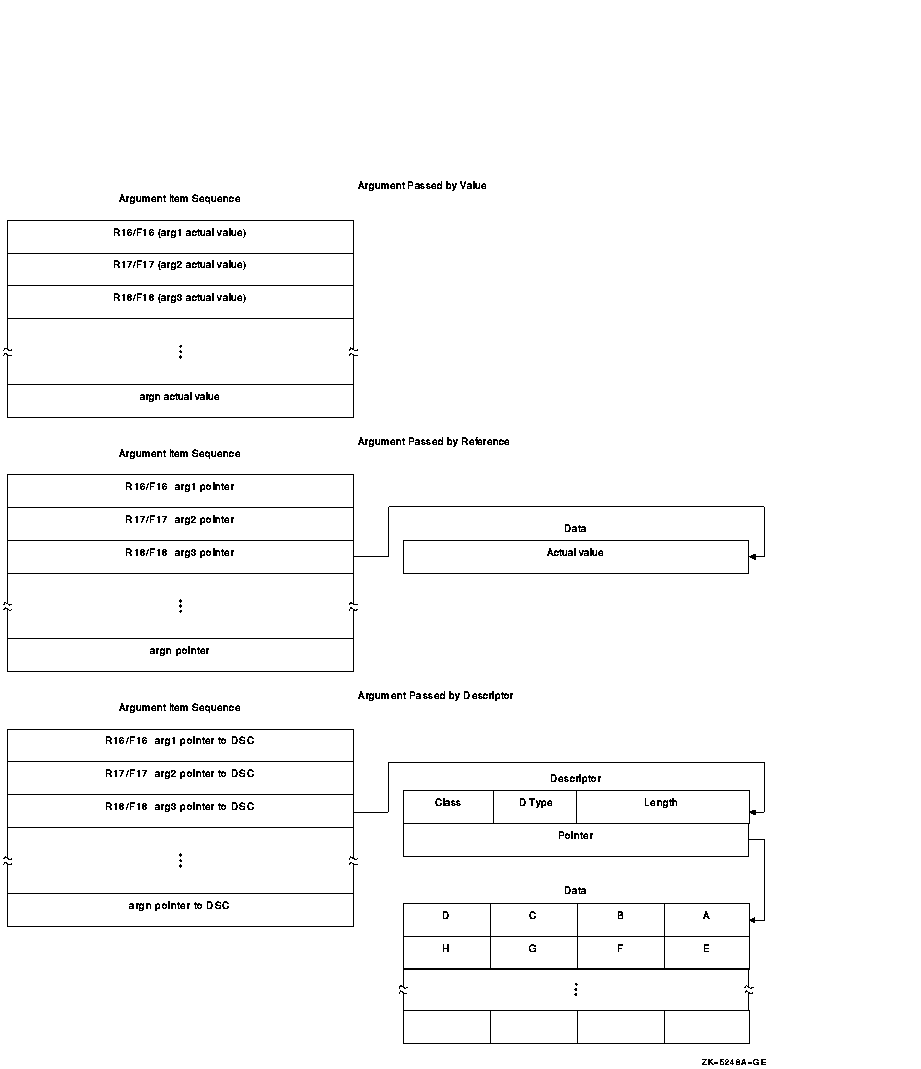
Figure 2-8 VAX Procedure Argument-Passing Mechanisms
OpenVMS programming reference manuals provide a description of each OpenVMS system routine that indicates how each argument is to be passed. Phrases such as "an address" and "address of a character string descriptor" identify reference and descriptor arguments, respectively. Terms like "Boolean value," "number," "value," and "mask" indicate an argument that is passed by value.
| Previous | Next | Contents | Index |
![[Go to the documentation home page]](../../images/buttons/bn_site_home.gif)
![[How to order documentation]](../../images/buttons/bn_order_docs.gif)
![[Help on this site]](../../images/buttons/bn_site_help.gif)
![[How to contact us]](../../images/buttons/bn_comments.gif)
|
| privacy and legal statement | ||
| 5843PRO_002.HTML | ||