![[Compaq]](../../images/compaq.gif)
![[Go to the documentation home page]](../../images/buttons/bn_site_home.gif)
![[How to order documentation]](../../images/buttons/bn_order_docs.gif)
![[Help on this site]](../../images/buttons/bn_site_help.gif)
![[How to contact us]](../../images/buttons/bn_comments.gif)
![[OpenVMS documentation]](../../images/ovmsdoc_sec_head.gif)
| Document revision date: 19 July 1999 | |
![[Compaq]](../../images/compaq.gif) |
![[Go to the documentation home page]](../../images/buttons/bn_site_home.gif)
![[How to order documentation]](../../images/buttons/bn_order_docs.gif)
![[Help on this site]](../../images/buttons/bn_site_help.gif)
![[How to contact us]](../../images/buttons/bn_comments.gif)
|
![[OpenVMS documentation]](../../images/ovmsdoc_sec_head.gif)
|
|
| Previous | Contents | Index |
Achieving high availability is an ongoing process. How you manage your
OpenVMS Cluster system is just as important as how you configure it.
This section presents strategies for maintaining availability in your
OpenVMS Cluster configuration.
8.4.1 Strategies for Maintaining Availability
After you have set up your initial configuration, follow the strategies listed in Table 8-5 to maintain availability in OpenVMS Cluster system.
| Strategy | Description |
|---|---|
| Plan a failover strategy |
OpenVMS Cluster systems provide software support for failover between
hardware components. Be aware of what failover capabilities are
available and which can be customized for your needs. Determine which
components must recover from failure, and make sure that components are
able to handle the additional work load that may result from a failover.
Reference: Table 8-2 lists OpenVMS Cluster failover mechanisms and the levels of recovery that they provide. |
| Code distributed applications | Code applications to run simultaneously on multiple nodes in an OpenVMS Cluster system. If a node fails, the remaining members of the OpenVMS Cluster system are still available and continue to access the disks, tapes, printers, and other peripheral devices that they need. |
| Minimize change | Assess carefully the need for any hardware or software change before implementing it on a running node. If you must make a change, test it in a noncritical environment before applying it to your production environment. |
| Reduce size and complexity | After you have achieved redundancy, reduce the number of components and the complexity of the configuration. A simple configuration minimizes the potential for user and operator errors as well as hardware and software errors. |
| Set polling timers identically on all nodes |
Certain system parameters control the polling timers used to maintain
an OpenVMS Cluster system. Make sure these system parameter values are
set identically on all OpenVMS Cluster member nodes.
Reference: For information about these system parameters, see OpenVMS Cluster Systems. |
| Manage proactively | The more experience your system managers have, the better. Allow privileges for only those users or operators who need them. Design strict policies for managing and securing the OpenVMS Cluster system. |
| Use AUTOGEN proactively | With regular AUTOGEN feedback, you can analyze resource usage that may affect system parameter settings. |
| Reduce dependencies on a single server or disk | Distributing data across several systems and disks prevents one system or disk from being a single point of failure. |
| Implement a backup strategy | Performing frequent backup procedures on a regular basis guarantees the ability to recover data after failures. None of the strategies listed in this table can take the place of a solid backup strategy. |
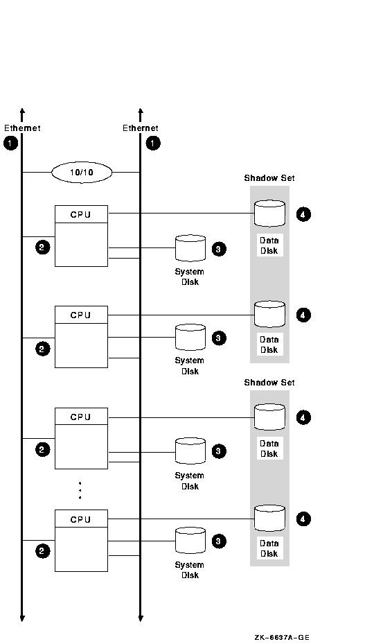
Figure 8-1 shows an optimal configuration for a small-capacity, highly available LAN OpenVMS Cluster system. Figure 8-1 is followed by an analysis of the configuration that includes:
Figure 8-1 LAN OpenVMS Cluster System

8.5.1 Components
The LAN OpenVMS Cluster configuration in Figure 8-1 has the
following components:
| Part | Description |
|---|---|
| 1 |
Two Ethernet interconnects. For higher network capacity, use FDDI
interconnects instead of Ethernet.
Rationale: For redundancy, use at least two LAN interconnects and attach all nodes to all LAN interconnects. A single interconnect would introduce a single point of failure. |
| 2 |
Three to eight Ethernet-capable OpenVMS nodes.
Each node has its own system disk so that it is not dependent on another node. Rationale: Use at least three nodes to maintain quorum. Use fewer than eight nodes to avoid the complexity of managing eight system disks. Alternative 1: If you require satellite nodes, configure one or two nodes as boot servers. Note, however, that the availability of the satellite nodes is dependent on the availability of the server nodes. Alternative 2: For more than eight nodes, use a LAN OpenVMS Cluster configuration as described in Section 8.10. |
| 3 |
System disks.
System disks generally are not shadowed in LAN OpenVMS Clusters because of boot-order dependencies. Alternative 1: Shadow the system disk across two local controllers. Alternative 2: Shadow the system disk across two nodes. The second node mounts the disk as a nonsystem disk. Reference: See Section 11.2.4 for an explanation of boot-order and satellite dependencies. |
| 4 |
Essential data disks.
Use volume shadowing to create multiple copies of all essential data disks. Place shadow set members on at least two nodes to eliminate a single point of failure. |
This configuration offers the following advantages:
This configuration has the following disadvantages:
The configuration in Figure 8-1 incorporates the following strategies, which are critical to its success:
Follow these guidelines to configure a highly available multiple LAN cluster:
Reference: See Section 10.7.7 for information about
extended LANs (ELANs).
8.6.1 Selecting MOP Servers
When using multiple LAN adapters with multiple LAN segments, distribute the connections to LAN segments that provide MOP service. The distribution allows MOP servers to downline load satellites even when network component failures occur.
It is important to ensure sufficient MOP servers for both VAX and Alpha nodes to provide downline load support for booting satellites. By careful selection of the LAN connection for each MOP server (Alpha or VAX, as appropriate) on the network, you can maintain MOP service in the face of network failures.
8.6.2 Configuring Two LAN Segments
Figure 8-2 shows a sample configuration for an OpenVMS Cluster
system connected to two different LAN segments. The configuration
includes Alpha and VAX nodes, satellites, and two bridges.
Figure 8-2 Two-LAN Segment OpenVMS Cluster Configuration

The figure illustrates the following points:
Figure 8-3 shows a sample configuration for an OpenVMS Cluster system connected to three different LAN segments. The configuration also includes both Alpha and VAX nodes and satellites and multiple bridges.
Figure 8-3 Three-LAN Segment OpenVMS Cluster Configuration

The figure illustrates the following points:
Reference: See Section 11.2.4 for more information
about boot order and satellite dependencies in a LAN. See OpenVMS Cluster Systems
for information about LAN bridge failover.
8.7 Availability in a DSSI OpenVMS Cluster
Figure 8-4 shows an optimal configuration for a medium-capacity, highly available DSSI OpenVMS Cluster system. Figure 8-4 is followed by an analysis of the configuration that includes:
Figure 8-4 DSSI OpenVMS Cluster System

8.7.1 Components
The DSSI OpenVMS Cluster configuration in Figure 8-4 has the
following components:
| Part | Description |
|---|---|
| 1 |
Two DSSI interconnects with two DSSI adapters per node.
Rationale: For redundancy, use at least two interconnects and attach all nodes to all DSSI interconnects. |
| 2 |
Two to four DSSI-capable OpenVMS nodes.
Rationale: Three nodes are recommended to maintain quorum. A DSSI interconnect can support a maximum of four OpenVMS nodes. Alternative 1: Two-node configurations require a quorum disk to maintain quorum if a node fails. Alternative 2: For more than four nodes, configure two DSSI sets of nodes connected by two LAN interconnects. |
| 3 |
Two Ethernet interconnects.
Rationale: The LAN interconnect is required for DECnet--Plus communication. Use two interconnects for redundancy. For higher network capacity, use FDDI instead of Ethernet. |
| 4 |
System disk.
Shadow the system disk across DSSI interconnects. Rationale: Shadow the system disk across interconnects so that the disk and the interconnect do not become single points of failure. |
| 5 |
Data disks.
Shadow essential data disks across DSSI interconnects. Rationale: Shadow the data disk across interconnects so that the disk and the interconnect do not become single points of failure. |
The configuration in Figure 8-4 offers the following advantages:
This configuration has the following disadvantages:
The configuration in Figure 8-4 incorporates the following strategies, which are critical to its success:
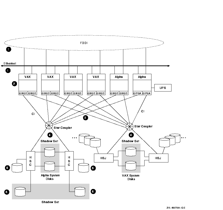
Figure 8-5 shows an optimal configuration for a large-capacity, highly available CI OpenVMS Cluster system. Figure 8-5 is followed by an analysis of the configuration that includes:
Figure 8-5 CI OpenVMS Cluster System

The CI OpenVMS Cluster configuration in Figure 8-5 has the following components:
| Part | Description |
|---|---|
| 1 |
Two LAN interconnects.
Rationale: The additional use of LAN interconnects is required for DECnet--Plus communication. Having two LAN interconnects---Ethernet or FDDI---increases redundancy. For higher network capacity, use FDDI instead of Ethernet. |
| 2 |
Two to 16 CI capable OpenVMS nodes.
Rationale: Three nodes are recommended to maintain quorum. A CI interconnect can support a maximum of 16 OpenVMS nodes. Reference: For more extensive information about the CIPCA, see Appendix C. Alternative: Two-node configurations require a quorum disk to maintain quorum if a node fails. |
| 3 |
Two CI interconnects with two star couplers.
Rationale: Use two star couplers to allow for redundant connections to each node. |
| 4 |
Critical disks are dual ported between CI storage controllers.
Rationale: Connect each disk to two controllers for redundancy. Shadow and dual port system disks between CI storage controllers. Periodically alternate the primary path of dual-ported disks to test hardware. |
| 5 |
Data disks.
Rationale: Single port nonessential data disks, for which the redundancy provided by dual porting is unnecessary. |
| 6 |
Essential data disks are shadowed across controllers.
Rationale: Shadow essential disks and place shadow set members on different HSCs to eliminate a single point of failure. |
This configuration offers the following advantages:
This configuration has the following disadvantage:
The configuration in Figure 8-5 incorporates the following strategies, which are critical to its success:
8.9 Availability in a MEMORY CHANNEL OpenVMS Cluster
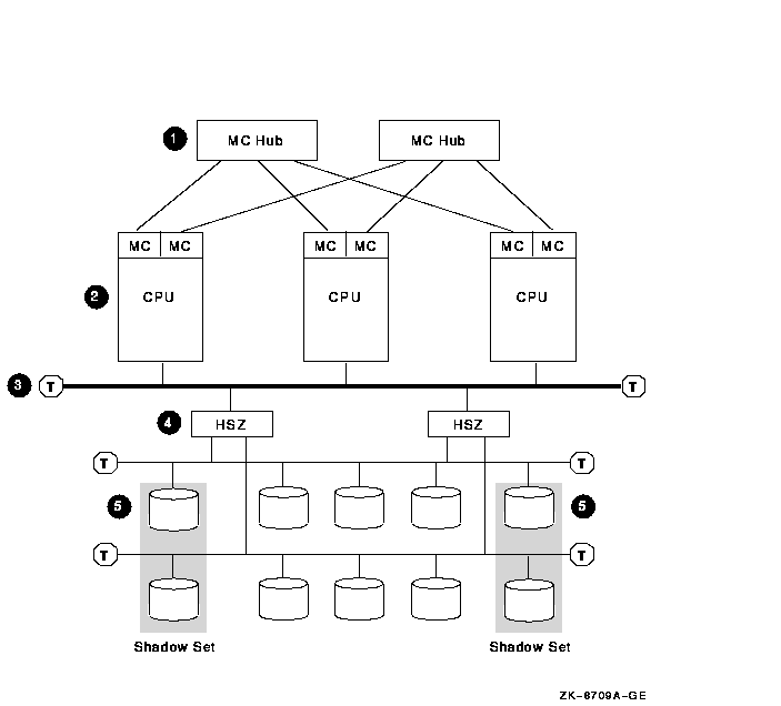
Figure 8-6 shows a highly available MEMORY CHANNEL (MC) cluster
configuration. Figure 8-6 is followed by an analysis of the
configuration that includes:
Figure 8-6 MEMORY CHANNEL Cluster

The MEMORY CHANNEL configuration shown in Figure 8-6 has the following components:
| Part | Description |
|---|---|
| 1 |
Two MEMORY CHANNEL hubs.
Rationale: Having two hubs and multiple connections to the nodes prevents having a single point of failure. |
| 2 |
Three to eight MEMORY CHANNEL nodes.
Rationale: Three nodes are recommended to maintain quorum. A MEMORY CHANNEL interconnect can support a maximum of eight OpenVMS Alpha nodes. Alternative: Two-node configurations require a quorum disk to maintain quorum if a node fails. |
| 3 |
Fast-wide differential (FWD) SCSI bus.
Rationale: Use a FWD SCSI bus to enhance data transfer rates (20 million transfers per second) and because it supports up to two HSZ controllers. |
| 4 |
Two HSZ controllers.
Rationale: Two HSZ controllers ensure redundancy in case one of the controllers fails. With two controllers, you can connect two single-ended SCSI buses and more storage. |
| 5 |
Essential system disks and data disks.
Rationale: Shadow essential disks and place shadow set members on different SCSI buses to eliminate a single point of failure. |
This configuration offers the following advantages:
This configuration has the following disadvantage:
| Previous | Next | Contents | Index |
![[Go to the documentation home page]](../../images/buttons/bn_site_home.gif)
![[How to order documentation]](../../images/buttons/bn_order_docs.gif)
![[Help on this site]](../../images/buttons/bn_site_help.gif)
![[How to contact us]](../../images/buttons/bn_comments.gif)
|
| privacy and legal statement | ||
| 6318PRO_011.HTML | ||