| Previous | Contents | Index |
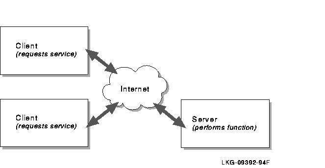
Host-to-host communication takes place between two processes. A process is a program that executes on a host. Any process that offers a service to another process over the network is known as a server. Any process that requests a service from another process over the network is known as a client. Clients request a service from the server and wait for the result. The server performs that service as if it were local to the client. Servers are shared processes that support multiple clients.
Figure 2-1 shows a typical client/server relationship.
Figure 2-1 Client/Server Relationship
Each host in an internet must have a unique Internet Protocol (IP) address. To communicate with a remote host, a local user must know the IP address of the remote host and both hosts must reside on the same internet.
The IP address consists of 32 bits (equivalent to 4 bytes or octets) of information. The 4 bytes are usually expressed in dotted--decimal notation with each byte a number between 0 and 255. For example, 98.0.2.65 is a valid IP address.
The 4-byte IP address is divided into two parts: the network
ID and the host ID. Within the same network,
the IP address of each host has the same network ID but a unique host
ID. For example, 201.233.20.125 and 201.233.20.130 are two separate
hosts on the same network (201.233.20 is the network ID and 125 and 130
the host IDs of the two hosts).
2.4.1 The Class Assignment Scheme for IP Addresses
In the past, IP addresses were organized into three classes, depending on the size of the network they represent: Class A, Class B, and Class C. Class A networks are extremely large; each Class A network can consist of more than 16 million hosts. Class B networks are smaller with a maximum of 65,534 hosts, and Class C networks must contain fewer than 254 hosts. (These numbers are theoretical. In practice, Class A and Class B networks are usually divided into subnets, which significantly reduces the number of hosts they contain.)
Given that each IP address is 4 bytes, you can tell the relative size of a network based on its IP address, as follows:
See Table 2-1 for examples of the network address for the three classes of networks.
| Class | First Byte | Second Byte | Third Byte | Fourth Byte | Example |
|---|---|---|---|---|---|
| A | 1--126 | x 1 | x 1 | x 1 | 103. x.x.x 1 |
| B | 128--191 | 0--255 | x 1 | x 1 | 153.200. x.x 1 |
| C | 192--223 | 0--255 | 0--255 | x 1 | 203.120.2. x 1 |
The InterNIC is the central organization that assigned network addresses to other organizations, which in turn assigned the host IDs represented by x in Table 2-1. Each organization was responsible for making sure that all attached hosts were properly numbered. Currently, only Class C networks are available.
These days it is more likely that you will obtain your IP addresses
from your Internet service provider (ISP) or your company's data
communications department.
2.4.2 CIDR Helps Solve Problems Associated with the Class Addressing Scheme
Although the A, B, and C class addressing scheme was easy to understand and implement, it did not foster the efficient allocation of address space. Instead, this scheme resulted in a premature depletion of Class B network space and left medium-sized organizations with Class C space causing the rapid growth in the size of the global routing tables.
Classless Interdomain Routing (CIDR) was developed to keep the Internet from running out of address space, replacing the old Class assignment scheme. Under CIDR, only the amount of address space that is actually needed is allocated.
CIDR eliminates the traditional concept of Class A, Class B, and Class C network addresses and replaces them with the generalized concept of a network prefix. In a classless environment, prefixes are viewed as bit-wise contiguous blocks of the IP address space. Because CIDR doesn't limit network identifiers to 8, 16, or 24 bits, blocks of addresses can be assigned for very small networks or for very large networks.
Routers use the network prefix, rather than the first 3 bits of the IP address, to determine the dividing point between the network number and the host number. As a result, CIDR supports the deployment of arbitrarily sized networks rather than the standard 8-bit, 16- bit, or 24-bit network numbers associated with classful addressing.
In the CIDR model, each piece of routing information is advertised with a bit mask (or prefix-length). The prefix-length is a way of specifying the number of leftmost contiguous bits in the network-portion of each routing table entry. For example, a network with 20 bits of network-number and 12-bits of host-number would be advertised with a 20-bit prefix length (a /20). The IP address advertised with the /20 prefix could be a former Class A, Class B, or Class C address. Routers that support CIDR rely only on the prefix-length information provided with the route.
Another problem related to the waste of address space with the Class A, B, and C allocation scheme was the growing size of Internet global routing tables. As the number of networks on the Internet increased, so did the number of routes. Global backbone Internet routers were fast approaching their limit on the number of routes they could support.
CIDR helps solve this problem by enabling route
aggregation. With route aggregation, a single high-level route
entry can represent many lower-level routes in the global routing
tables thus minimizing route table entries.
2.4.3 Example of IP Addresses
Figure 2-2 shows an example of assigned IP addresses and names for an internet.
Figure 2-2 IP Addresses and Names of a Sample Internet
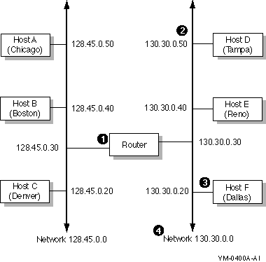
Although the name and address of a host can change, they usually remain
stable for extended time periods.
2.4.4 Network Byte Order
Internet packets carry binary numbers that specify information such as destination addresses and packet lengths, which must be understood by both the sending and receiving hosts. Different machines, however, store 32-bit integers in different ways. The two most common ways are called Little Endian and Big Endian. With Little Endian style, the lowest memory address contains the low-order byte of the integer whereas with Big Endian, it contains the high-order byte of the integer. Thus, direct copying of bytes from one machine to another may change the value of the number.
To solve this problem, the Internet community has defined the Big Endian style as the network standard byte order that all machines must use for binary fields in internet packets. Each host converts binary items from the local representation to network standard byte order before it sends a packet and converts the packet back to the local representation when a packet is received.
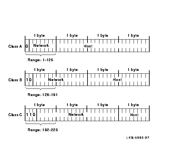
In the network standard byte order, the high-order bits in the network number designate the network class of the IP address. For a Class A network, the first high-order bit is 0. For a Class B network, the first two high-order bits are 10. For a Class C network, the first three high-order bits are 110.
Figure 2-3 shows the bit positions of the IP address for the three network classes.
Figure 2-3 IP Network Classes
Subnetting hides the details of internal network organization to external routers and reduces the size of the internet's routing tables. To reach any host within a subnet, external routers only need to know the path to a single host. Subnet routing requires a different interpretation of IP addresses. A certain number of bits are taken from the octets in the host part of the address and used to specify subnet information. This is called a subnet mask.
The subnet mask informs the system which high-order bits of the IP address to interpret as the network ID and subnet ID. The remaining low-order bits refer to the host ID. A subnet mask is a 32-bit number. There is a one-to-one correspondence between the 32 bits in the subnet mask and the 32 bits in the IP address. (A subnet mask may also be referred to as a network mask.)
For each bit in the subnet mask that is turned on (binary 1), the corresponding bit position in the IP address is interpreted as part network ID and subnet ID.
The decimal number 255 is 11111111 in binary notation. The value 255 means that an entire 8-bit field is turned on because each bit position is a 1. Generally, the entire 8-bit field is turned either on (255) or off (0). Values other than 255 or 0 can be used. However, by using 255 or 0, you make it easier for users to differentiate between the network, host, and subnet fields.
If the subnet mask bit position is part of the host ID and is turned on, the corresponding bit in the IP address is interpreted as part of the subnet address. If the subnet mask bit position is part of the host ID and is turned off, the corresponding bit in the IP address is interpreted as part of the host ID.
All bits in the first (leftmost) byte of the subnet mask must be turned on (decimal value of 255, binary value of 11111111), because the first byte of the IP address must always be interpreted as the network ID regardless of whether there are subnets. If a bit in the first byte of the subnet mask is turned off, part of the network ID of the IP address is interpreted as part of the host ID. This may cause errors.
The second and third bytes of the new mask are usually either 255 or 0, depending on how the IP address is to be interpreted. The fourth byte is usually 0, to indicate that the fourth byte of the IP address is part of the host ID.
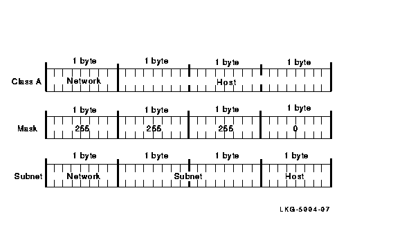
Figures 2-4 and 2-5 illustrate the way different subnet masks affect the subnet address. As illustrated in Figure 2-4, a Class A subnet mask can be 255.255.0.0. When the subnet mask is 255.255.0.0, the first byte is the network ID, the second byte is the subnet ID, and the third and fourth bytes are the host ID.
Figure 2-4 Class A Network Mask, Example 1
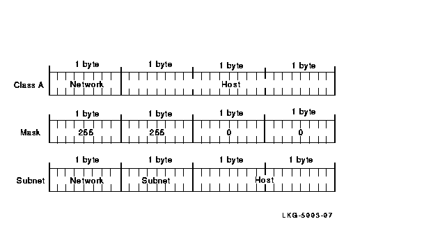
Figure 2-5 shows a Class A network with a subnet mask of 255.255.255.0. If the subnet mask is 255.255.255.0, the first byte is the network ID, the second and third bytes are the subnet ID, and the fourth byte is the host ID.
Figure 2-5 Class A Network Mask, Example 2
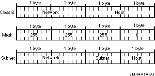
If a Class B network uses 255.255.255.0 (as shown in Figure 2-6) for a subnet mask, the first and second bytes are the network ID, the third byte is the subnet ID, and the fourth byte is the host ID.
Figure 2-6 Class B Network Mask
Normally, Class C networks do not have subnets, because only 8 bits are allocated for the host part of the IP address. Eight bits may not be enough to divide between a subnet address and a host address.
The default subnet masks for each class are as follows:
The broadcast mask interprets the IP address as a broadcast address. The broadcast address allows messages to be sent to all the hosts on the network at the same time. If you use subnets, all the hosts on the same subnet must have the same IP broadcast address.
The default format of the broadcast address consists of the network ID followed by all 1s. The network ID includes the subnet, if there is one. Although the all-zeroes method of forming a broadcast address has not been used for many years, at times, you may need to specify an alternate broadcast address for testing or for compatibility purposes. The default is usually adequate.
If you know the IP address and the subnet mask for a particular host,
you can determine the broadcast address by using the following formula:
(NOT networkmask) OR (internetaddress)
For example, if a host has an IP address of 128.50.100.100 and its network mask is 255.255.0.0 (the default), its broadcast mask is 128.50.255.255. The NOT of its subnet mask is 0.0.255.255. You then substitute the first two fields of the IP address for the two 0s to get the broadcast address.
Table 2-2 lists examples of broadcast addresses.
| Host IP Address | Host Number | Network Class | Network Number | Network Mask | Broadcast Address |
|---|---|---|---|---|---|
| 3.0.0.10 | 10 | A | 3. | 255.0.0.0 | 3.255.255.255 |
| 11.1.0.12 1 | 12 | A | 11.1. | 255.255.0.0 | 11.1.255.255 |
| 129.39.0.15 | 15 | B | 129.39. | 255.255.0.0 | 129.39.255.255 |
| 128.45.2.8 1 | 2.8 | B | 128.45. | 255.255.0.0 | 128.45.2.255 |
| 192.0.1.8 | 8 | C | 192.0.1. | 255.255.255.0 | 192.0.1.255 |
| 192.0.1.223 | 223 | C | 192.0.1. | 255.255.255.0 | 192.0.1.255 |
Routing is the process of moving information, in the form of datagrams, from one host to another over the network. Under the class addressing scheme, a router receives an IP packet and extracts its destination address. The destination is classified (literally) by examining its first one-to-four bits. Once the address's class is determined, it is broken down into network and host bits. Routers ignore the host bits, and only need to match the network bits to find a route to the network. Once a packet reaches the target network, its host field is examined for final delivery.
Figure 2-7 shows internet routing.
Figure 2-7 Internet Routing
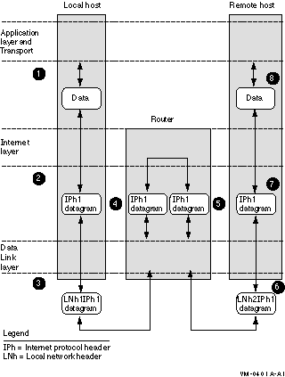
Internet routing follows this progression:
LANs and WANs interconnected by IP routers form a group of networks called an internet. For administrative purposes, an internet is divided into autonomous systems. An autonomous system (AS) is simply a collection of routers and hosts.
Routers inside an autonomous system use an interior gateway protocol to communicate network topology changes to each other. Routers in separate autonomous systems use an exterior gateway protocol to communicate. The TCP/IP Services product supports three dynamic interior protocols: RIP Version 1, RIP Version 2, and OSPF; and two exterior protocols: BGP and EGP.
The following sections provide more information.
2.5.1.1 Routing Information Protocol (RIP)
The Routing Information Protocol (RIP) enables routers in the same
autonomous system to exchange routing information by means of periodic
RIP updates. Routers transmit their own RIP updates to neighboring
networks and listen for RIP updates from the routers on those
neighboring networks. Routers use the information in the RIP updates to
keep their internal routing tables current. For RIP, the "best" path to
a destination is the shortest path (the path with the fewest hops). RIP
computes distance as a metric, usually the number of hops (or routers)
from the origin network to the target network.
2.5.1.2 Open Shortest Path First (OSPF) Protocol
The Open Shortest Path First (OSPF) protocol is an IGP used in large networks. Using a link state algorithm, OSPF exchanges routing information between routers in an autonomous system; then routers synchronize their databases. Once the routers are synchronized and the routing tables are built, the routers will forward topology information only in response to some topological change. For OSPF, the "best" path to a destination is the path that offers the least cost metric delay. In OSPF, cost metrics are configurable, allowing you to specify preferred paths and to load balance equal cost routes.
OSPF supports CIDR and can carry supernet advertisements within a
routing domain.
2.5.1.3 Border Gateway Protocol (BGP)
The Border Gateway Protocol (BGP) is an exterior gateway protocol used to exchange network reachability information with other BGP systems. BGP routers form relationships with other BGP routers. BGP routers transmit and receive current routing information over a reliable Transport layer connection. Because a reliable transport mechanism is used, periodic updates are not necessary.
BGP updates contain "path attributes" that describe the route to a set
of destination networks. When multiple paths are available, BGP
compares these path attributes to choose the preferred path.
2.5.1.4 Exterior Gateway Protocol (EGP)
The Exterior Gateway Protocol (EGP-2) is an exterior gateway protocol used to exchange network reachability information between routers in different autonomous systems. (A protocol, such as RIP or OSPF, is used within an AS to facilitate the communication of routing information within the autonomous system.) The routers that serve as the end points of a connection between two autonomous systems run an exterior gateway protocol such as EGP.
Routers establish EGP neighbor relationships to periodically exchange reliable network reachability information. The router uses this information to maintain a list of gateways, the networks the gateways can reach, and the corresponding distances.
| Previous | Next | Contents | Index |