![[Compaq]](../../images/compaq.gif)
![[Go to the documentation home page]](../../images/buttons/bn_site_home.gif)
![[How to order documentation]](../../images/buttons/bn_order_docs.gif)
![[Help on this site]](../../images/buttons/bn_site_help.gif)
![[How to contact us]](../../images/buttons/bn_comments.gif)
![[OpenVMS documentation]](../../images/ovmsdoc_sec_head.gif)
| Document revision date: 30 March 2001 | |
![[Compaq]](../../images/compaq.gif) |
![[Go to the documentation home page]](../../images/buttons/bn_site_home.gif)
![[How to order documentation]](../../images/buttons/bn_order_docs.gif)
![[Help on this site]](../../images/buttons/bn_site_help.gif)
![[How to contact us]](../../images/buttons/bn_comments.gif)
|
![[OpenVMS documentation]](../../images/ovmsdoc_sec_head.gif)
|
|
| Previous | Contents | Index |
Volume Shadowing for OpenVMS provides data availability across the full range of configurations---from single nodes to large OpenVMS Cluster systems---so you can provide data availability where you need it most.
There are no restrictions on the location of shadow set members beyond the valid disk configurations defined in the SPDs for the OpenVMS operating system and for OpenVMS Cluster systems:
If an individual disk volume is already mounted as a member of an
active shadow set, the disk volume cannot be mounted as a standalone
disk on another node.
1.4.1 Maximum Number of Shadow Sets
You can mount a maximum of 500 disks in two- or three-member shadow
sets on a standalone system or in an OpenVMS Cluster system. A limit of
10,000 single member shadow sets is allowed on a standalone system or
on an OpenVMS Cluster system. Dismounted shadow sets, unused shadow
sets, and shadow sets with no write bitmaps allocated to them are
included in this total. These limits are independent of controller and
disk type. The shadow sets can be mounted as public or private volumes.
1.4.2 Shadowing System Disks
You can shadow system disks as well as data disks. Thus, a system disk need not be a single point of failure for any system that boots from that disk. System disk shadowing becomes especially important for OpenVMS Cluster systems that use a common system disk from which multiple computers boot. Volume shadowing makes use of the OpenVMS distributed lock manager, and the quorum disk must be accessed before locking is enabled. Note that you cannot shadow quorum disks.
Alpha and VAX systems can share data on shadowed data disks, but
separate system disks are required --- one for Alpha systems and one
for VAX systems.
1.4.2.1 Obtaining Dump Files of Shadowed System Disk When Minicopy Is Used
Additional steps are required to access the dump file from a system disk shadow set in which a minicopy operation was used to return a member to the shadow set.
After a crash dump is written to one member of a system disk shadow set, if minicopy is used to return a member to that shadow set, then you must take certain steps to properly analyze or copy that SYSDUMP.DMP file. When the primitive file system writes a crash dump, the writes are not recorded in the write bitmap data structure. Therefore, perform the following steps:
SET DEVICE/READ_COST=nnn $allo_class$ddcu |
$ SET DEVICE /READ_COST=0 DSAnnnn |
SDA and CLUE will be modified in a future release. When those modifications are done, you will not need to adjust the read cost values of the shadow set members to accurately read the dump file. |
To use the minicopy feature, introduced in OpenVMS Version 7.3, every
node in the cluster must use a version of OpenVMS that contains this
feature. Soon after the release of OpenVMS Version 7.3, an update for
OpenVMS Version 7.2-xx will be available, which will include
support for minicopy. Until then, minicopy cannot be used in a
mixed-version OpenVMS Cluster system.
1.4.4 Using Minicopy in a Mixed-Architecture OpenVMS Cluster System
If you intend to use the minicopy feature in a mixed-architecture
OpenVMS Cluster system, Compaq advises you to set the SHADOW_MAX_COPY
system parameter to zero on all VAX systems. This setting prevents a
copy from being performed on a VAX when the intent was to perform a
minicopy on an Alpha. In a mixed-architecture cluster, it is possible,
although highly unlikely, that a VAX system could be assigned the task
of adding a member to a shadow set. Because a VAX system cannot perform
a minicopy, it would perform a full copy instead. For more information
about SHADOW_MAX_COPY, see Section 3.2.
1.4.5 Shadow Sets, Bound Volume Sets, and Stripe Sets
Shadow sets also can be constituents of a bound volume set or a stripe
set. A bound volume set consists of one or more disk volumes that have
been bound into a volume set by specifying the /BIND qualifier with the
MOUNT command. Section 1.5 describes shadowing across OpenVMS Cluster
systems. Chapter 9 contains more information about striping and how
RAID (redundant arrays of independent disks) technology relates to
volume shadowing.
1.5 Shadowing Disks Across an OpenVMS Cluster System
The host-based implementation of volume shadowing allows disks that are connected to multiple physical controllers to be shadowed in an OpenVMS Cluster system. There is no requirement that all members of a shadow set be connected to the same controller. Controller independence allows you to manage shadow sets regardless of their controller connection or their location in the OpenVMS Cluster system and helps provide improved data availability and flexible configurations.
For clusterwide shadowing, members can be located anywhere in an OpenVMS Cluster system and served by MSCP servers across any supported OpenVMS Cluster interconnect, including the CI (computer interconnect), Ethernet (10/100 and Gigabit), ATM, Digital Storage Systems Interconnect (DSSI), and Fiber Distributed Data Interface (FDDI). For example, OpenVMS Cluster systems using FDDI and wide area network services can be hundreds of miles apart, which further increases the availability and disaster tolerance of a system.
Figure 1-2 shows how shadow-set members are on line to local adapters located on different nodes. In the figure, a disk volume is local to each of the nodes ATABOY and ATAGRL. The MSCP server provides access to the shadow set members over the Ethernet. Even though the disk volumes are local to different nodes, the disks are members of the same shadow set. A member that is local to one node can be accessed by the remote node via the MSCP server.
Figure 1-2 Shadow Sets Accessed Through the MSCP Server
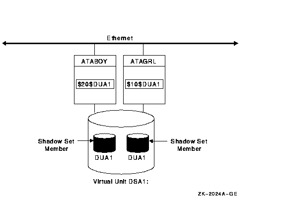
The shadowing software maintains shadow sets in a distributed fashion on each node that mounts the shadow set in the OpenVMS Cluster system. In an OpenVMS Cluster environment, each node creates and maintains shadow sets independently. The shadowing software on each node maps each shadow set, represented by its virtual unit name, to its respective physical units. Shadow sets are not served to other nodes. When a shadow set must be accessed by multiple nodes, each node creates an identical shadow set. The shadowing software maintains clusterwide membership coherence for shadow sets mounted on multiple nodes.
For shadow sets that are mounted on an OpenVMS Cluster system, mounting
or dismounting a shadow set on one node in the cluster does not affect
applications or user functions executing on other nodes in the system.
For example, you can dismount the shadow set from one node in an
OpenVMS Cluster system and leave the shadow set operational on the
remaining nodes on which it is mounted.
1.6 Installation
Volume Shadowing for OpenVMS is a System Integrated Product (SIP) that you install at the same time that you install the operating system. Volume Shadowing requires its own license that is separate from the OpenVMS base operating system license. To use the volume shadowing software, you must install this license. All nodes booting from shadowed system disks must have shadowing licensed and enabled. See the instructions included in your current OpenVMS upgrade and installation manual.
See Section 3.1 for more information about licensing Volume Shadowing for OpenVMS.
System availability is a critical requirement in most computing environments. A dependable environment enables users to interact with their system when they want and in the way they want.
A key component of overall system availability is availability or accessibility of data. Volume Shadowing for OpenVMS provides high levels of data availability by allowing shadow sets to be configured on a single-node system or on an OpenVMS Cluster system, so that continued access to data is possible despite failures in the disk media, disk drive, or disk controller. For shadow sets whose members are local to different OpenVMS Cluster nodes, if one node serving a shadow set member shuts down, the data is still accessible through an alternate node.
Although you can create a virtual unit, the system representation of a shadow set, that consists of only one disk volume, you must mount two or more disk volumes in order to "shadow"---maintain multiple copies of the same data. This configuration protects against either failure of a single disk drive or deterioration of a single volume. For example, if one member fails out of a shadow set, the remaining member can be used as a source disk whose data can be accessed by applications at the same time the data is being copied to a newly mounted target disk. Once the data is copied, both disks contain identical information and the target disk becomes a source member of the shadow set.
Using two controllers provides a further guarantee of data availability in the event of a single-controller failure. When setting up a system with volume shadowing, you should connect each disk drive to a different controller I/O channel whenever possible. Separate connections help protect against either failure of a single controller or of the communication path used to access it.
Using an OpenVMS Cluster system (as opposed to a single-node environment) and multiple controllers provides the greatest data availability. Disks that are connected to different local controllers and disks that are MSCP-served by other OpenVMS systems can be combined into a single shadow set, provided the disks are compatible and no more than three are combined.
Figure 2-1 provides a qualitative, high-level classification of how you can achieve increasing levels of physical data availability in different types of configurations.
Figure 2-1 Levels of Availability
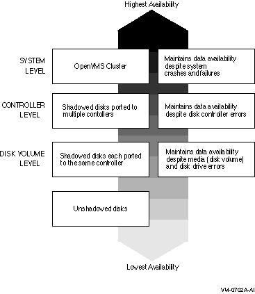
Section 2.1 describes how you can configure your shadowed system to
achieve high data availability despite physical failures.
2.1 Repair and Recovery from Failures
Volume shadowing failures, some of which are automatically recoverable by the volume shadowing software, are grouped into the following categories:
The handling of shadow set recovery and repair depends on the type of failure that occurred and the hardware configuration. In general, devices that are inaccessible tend to fail over to other controllers whenever possible. Otherwise, they are removed from the shadow set. Errors that occur as a result of media defects can often be repaired automatically by the volume shadowing software.
Table 2-1 describes these failure types and recovery mechanisms.
| Type | Description |
|---|---|
| Controller error | Results from a failure in the controller. If the failure is recoverable, processing continues and data availability is not affected. If the failure is nonrecoverable, shadow set members connected to the controller are removed from the shadow set, and processing continues with the remaining members. In configurations where disks are dual-pathed between two controllers, and one controller fails, the shadow set members fail over to the remaining controller and processing continues. |
| Device error | Signifies that the mechanics or electronics in the device failed. If the failure is recoverable, processing continues. If the failure is nonrecoverable, the node that detects the error removes the device from the shadow set. |
| Data errors |
Results when a device detects corrupt data. Data errors usually result
from media defects that do not cause the device to be removed from a
shadow set. Depending on the severity of the data error (or the degree
of media deterioration), the controller:
When data cannot be corrected by the controller, volume shadowing replaces the lost data by retrieving it from another shadow set member and writing the data to a different LBN of the member with the incorrect data. This repair operation is synchronized within the cluster and with the application I/O stream. |
| Connectivity failures |
When a connectivity failure occurs, the first node to detect the
failure must decide how to recover from the failure in a manner least
likely to affect the availability or consistency of the data. As each
node discovers the recoverable device failure, it determines its course
of action as follows:
|
To illustrate the varyious levels of data availability obtainable through Volume Shadowing for OpenVMS, this section provides a representative sample of hardware configurations. Figures 2-2 through 2-7 show possible system configurations for shadow sets. The hardware used to describe the sample systems, while intended to be representative, is hypothetical; they should be used only for general observations about availability and not as a suggestion for any specific configurations or products.
In all of the following examples, the shadow set members use the $allocation-class$ddcu: naming convention. The virtual unit uses the DSAn: format, where n represents a number between 0 and 9999. These naming conventions are described in more detail in Section 4.2.
Figure 2-2 shows one system with one host-based adapter (HBA). The shadow set consists of three disks. This configuration provides coverage against media errors and against the failure of one or two disks.
Figure 2-2 Configuration of a Shadow Set (One System, One Adapter)
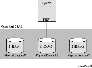
Figure 2-3 shows one system with two adapters. In this configuration, each disk in the shadow set is connected to a different adapter.
In addition to providing coverage against media errors or disk failures, this type of configuration provides continued access to data in spite of the failure of either one of the adapters.
Figure 2-3 Configuration of a Shadow Set (One System, Two Adapters)
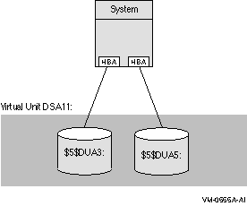
Figure 2-4 shows two systems, both connected to the same three-member shadow set. Each shadow set member is connected by dual paths to two adapters. The shadow set is accessible with either one or both systems operating. In this configuration, a disk can be on line to only one adapter at a time. For example, $2$DKA5 is on line (primary path) to System A. As a result, System B accesses $2$DKA5 by means of the MSCP server on System A. If System A fails, $2$DKA5 fails over to the adapter on System B.
Different members of the shadow set can fail over between adapters independently of each other. The satellite nodes access the shadow set members by means of the MSCP servers on each system. Satellites access all disks over primary paths, and failover is handled automatically.
Figure 2-4 Configuration of a Shadow Set (OpenVMS Cluster, Dual Adapters)
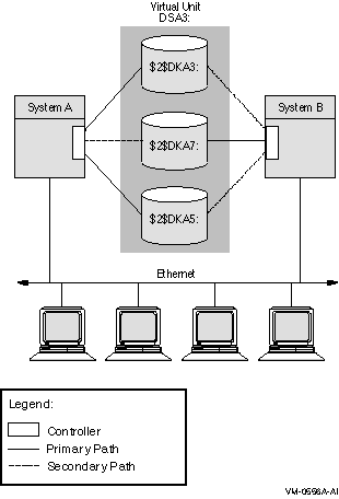
Figure 2-5 shows an OpenVMS Cluster system with two systems connected to multiple disks. Virtual units DSA1: and DSA2: represent the two shadow sets and are accessible through either system. This configuration offers both an availability and a performance advantage. The shadow sets in this configuration are highly available because the satellite nodes have access through either system. Thus, if one system fails, the satellites can access the shadowed disks through the remaining system.
In addition, this configuration offers a performance advantage by using another interconnect for I/O traffic that is separate from the Ethernet. In general, you can expect better I/O throughput from this type of configuration than from an Ethernet-only OpenVMS Cluster system.
Figure 2-5 Configuration of a Shadow Set (Highly Available OpenVMS Cluster)
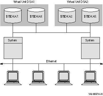
Figure 2-6 illustrates how shadowed disks can be located anywhere in an OpenVMS Cluster system. The figure presents a cluster system with three nodes, multiple HSJ controllers, and multiple shadow sets that are accessible by any node. The shadow sets are accessible when three nodes, two nodes, and, in some cases, only one node is operating. The exception is if System A and System B fail, leaving only System C running. In this case, access to the secondary star coupler is lost, preventing access to the DSA2: shadow set. Note that DSA1: would still be accessible, but it would be reduced to a one-member shadow set.
Figure 2-6 Configuration of a Shadow Set (Multiple Star Couplers, Multiple HSJ Controllers)
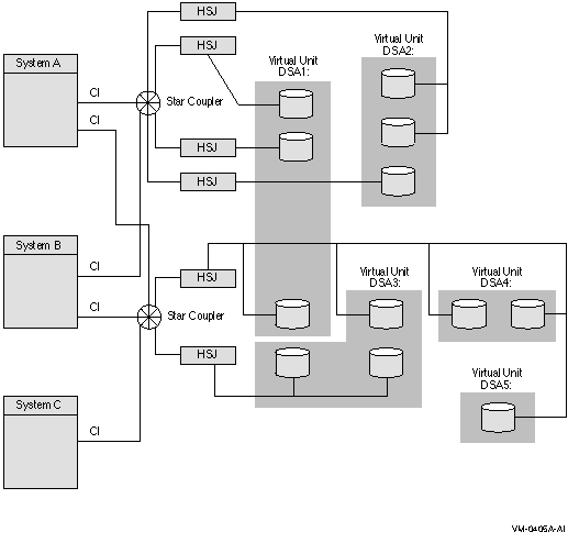
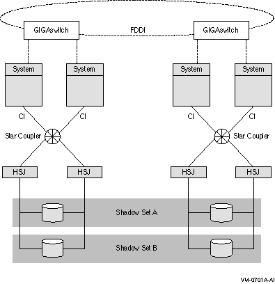
Figure 2-7 illustrates how the FDDI (Fiber Distributed Data Interface) interconnect allows you to shadow data disks over long distances. Members of each shadow set are configured between two distinct and widely separated locations --- a multiple-site OpenVMS Cluster system. The OpenVMS systems and shadowed disks in both locations function as a single OpenVMS Cluster system and shadow set configuration. If a failure occurs at either site, the critical data is still available at the remaining site.
Figure 2-7 Configuration of a Shadowed FDDI Multiple-Site Cluster
Systems other than satellite nodes are unable to boot from disks that are located remotely across an Ethernet or FDDI LAN. Therefore, these systems require local access to their system disk. Note that this restriction limits the ability to create system disk shadow sets across an FDDI or Ethernet LAN. |
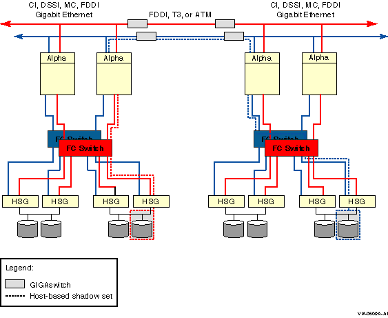
Figure 2-8 shows the use of shared Fibre Channel storage in a multiple-site OpenVMS Cluster system with shadowed disks. Members of the shadow set are configured between two widely separated locations. The configuration is similar to that in Figure 2-7, except that the systems at each site use shared Fibre Channel storage.
Figure 2-8 Configuration of a Shadowed Fibre Channel Multiple-Site Cluster
| Previous | Next | Contents | Index |
![[Go to the documentation home page]](../../images/buttons/bn_site_home.gif)
![[How to order documentation]](../../images/buttons/bn_order_docs.gif)
![[Help on this site]](../../images/buttons/bn_site_help.gif)
![[How to contact us]](../../images/buttons/bn_comments.gif)
|
| privacy and legal statement | ||
| 5423PRO_001.HTML | ||