![[Compaq]](../../images/compaq.gif)
![[Go to the documentation home page]](../../images/buttons/bn_site_home.gif)
![[How to order documentation]](../../images/buttons/bn_order_docs.gif)
![[Help on this site]](../../images/buttons/bn_site_help.gif)
![[How to contact us]](../../images/buttons/bn_comments.gif)
![[OpenVMS documentation]](../../images/ovmsdoc_sec_head.gif)
| Document revision date: 30 March 2001 | |
![[Compaq]](../../images/compaq.gif) |
![[Go to the documentation home page]](../../images/buttons/bn_site_home.gif)
![[How to order documentation]](../../images/buttons/bn_order_docs.gif)
![[Help on this site]](../../images/buttons/bn_site_help.gif)
![[How to contact us]](../../images/buttons/bn_comments.gif)
|
![[OpenVMS documentation]](../../images/ovmsdoc_sec_head.gif)
|
|
| Previous | Contents | Index |
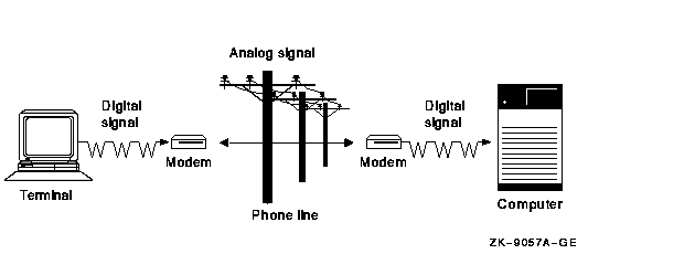
A modem converts a digital signal to an analog signal by modulating the digital information on a carrier signal; a modem converts analog to digital signals by demodulating---or extracting---digital information from analog signals on an analog transmission facility such as a telephone line. The two words MOdulator and DEModulator form the basis for the device name: modem.
Figure 8-1 represents communications between a terminal and a remote computer system, but the principles apply equally to communications between two computer systems. One modem converts digital to analog signals on the local end of the analog telephone connection, and another modem converts analog to digital signals on the remote end of the connection.
Figure 8-1 Basic Modem Configuration

Modems are always used in pairs; each one of the pair can act as both a transmitter and a receiver.
When configuring modems, you must check that:
Once a modem connection has been established, you can layer data communications over the connection. You can layer at least one, and sometimes more, of a wide variety of communications protocols on the basic asynchronous serial ASCII protocol that most modems provide. Point-to-Point Protocol (PPP) and asynchronous DECnet are examples of protocols that can operate over a modem link.
Table 8-3 lists references to OpenVMS documentation that discuss other communications protocols and topics relevant to the use of modems:
| Reference | Description |
|---|---|
| DECnet-Plus for OpenVMS Network Management | Explains the use of modems to establish a dynamic asynchronous DECnet connection between two nodes. Asynchronous DECnet is a protocol that can operate over a modem datalink. |
| Compaq TCP/IP Services for OpenVMS Management | Explains the use of modems to establish a serial connection using the PPP (Alpha only) and SLIP protocols and TCP/IP Services. |
| OpenVMS Guide to System Security | Discusses how to maintain the security of DECnet modem connections and dial-in modem lines. |
| TCP/IP Networking on OpenVMS Systems | Explains the use of PPP on OpenVMS Alpha and OpenVMS VAX to communicate with remote systems. |
| OpenVMS System Management Utilities Reference Manual: M--Z | Describes the PPP utiltity and associated commands. |
| Section 8.6.2 | Explains how to configure and manage virtual terminals. |
| OpenVMS DCL Dictionary and online help |
The DCL command SET HOST/DTE discusses the use of modems to connect to
a remote system.
The DCL commands CONNECT and DISCONNECT explain how to set up and disconnect virtual terminals. |
Direct and Indirect Connections
Part of the job of configuring a modem to a computer or a terminal is to decide what type of access the modem will have to your computing environment and which serial communications ports best meet your requirements.
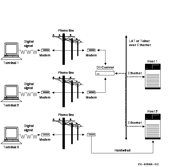
You can choose to connect a modem directly to a host system, or you can connect the modem indirectly to an intermediate network server device such as a DECserver. Explanations of these two types of connections follow.
With either type of connection, you cannot use the modem if the host or the server the modem is connected to is not operational.
Figure 8-2 depicts direct and indirect modem configurations. The remote devices T1 and T2 are indirectly connected to both Host1 and Host2 host computers using the DECserver and the LAT protocol; T3 is connected directly to Host2.
Figure 8-2 Direct and Indirect Modem Configurations

Once you decide which serial communications port to use, either on a
host or a terminal server, you need to determine the connectors and the
pinouts for the port and how to wire the modem to the port. Refer to
the documentation for the modem and for the port; also see
Section 8.7.2.
8.7.2 Setting Up Modems
Follow these steps to set up modems:
| Pinout | Description |
|---|---|
| Data Terminal Equipment (DTE) | Transmit information through pin 2, and receive information through pin 3, among other standardized pin assignments. |
| Data Communications Equipment (DCE) | Transmit information through pin 3, and receive information through pin 2, among other EIA-232 pin assignments. |
Straight-Through and Cross-Over Wiring
Descriptions of straight-through and cross-over wiring follow:
| Connector1 | Description |
|---|---|
| DB9 | A 9-pin connector, containing a row of four pins, and a row of five pins. The DB9 can have the EIA-574 commonly used on PC systems or an older standard connection used on MicroVAX consoles. |
| DB25 | A 25-pin connector, with a row of twelve pins and a row of thirteen pins. The DB25 typically uses the EIA-232 pinout and can be wired as Data Terminal Equipment (DTE) or as Data Communications Equipment (DCE). |
| MMJ | A 6-pin modular jack, which uses DEC-423 signaling, commonly referred to as DECconnect wiring. DECconnect wiring greatly simplifies wiring devices, as one need consider only the appropriate adapter for the device connection; the associated BC16E cabling is wired consistently. |
| Connector and Pinout | Example | Adapter1 | ||||||||
|---|---|---|---|---|---|---|---|---|---|---|
| A DB9 9-pin connector with an EIA-574 PC-compatible pinout | The DB9 connectors found on most PC, AlphaStation, and AlphaServer systems | Use the H8571-J or compatible MMJ adapter. | ||||||||
| A DB9 9-pin connector that predates the EIA-574 pinout | The console connector on various MicroVAX systems uses a pinout that predates the EIA-574 pinout | Use the H8575-B or compatible MMJ adapter. | ||||||||
| A DB25 25-pin connector with the EIA-232 wiring | The communications ports on many terminals |
Use the appropriate adapters from the following list,
2 or contact a Compaq sales representative or Compaq
reseller for information on adapters not listed below:
|
||||||||
| An 8-pin DIN (round) connector | Use the H8584-AB or compatible MMJ adapter. | |||||||||
| A Modified Modular Jack (MMJ) DECconnect socket | ||||||||||
MMJ Accessories
Table 8-7 lists order numbers and descriptions of some
DECconnect accessories available from Compaq.
| Order Number | Description |
|---|---|
|
BC16E-02
BC16E-10 BC16E-25 BC16E-50 BC16E-A0 |
DEC-423 (based on EIA-423) MMJ office cable, available in various lengths. |
| H8571-C | 25-pin male EIA-232 to DEC-423 DECconnect adapter. |
| H8571-E | DEC-423 DECconnect 25-pin adapter with jack screws. |
| H8571-J | 9-pin MMJ adapter. Used with the PC-compatible EIA-574 DB9 wiring. |
| H8572-00 | MMJ cable extender. Allows the direct connection of two BC16E cables. |
| H8575-A | Female 25-pin DEC-423 DECconnect MMJ to EIA-232 general-purpose adapter. |
| H8575-B | Female 9-pin DEC-423 DECconnect to printer adapter. Also used with the DB9 wiring found on some MicroVAX console ports. |
| H8584-AB | 8-pin DIN to DEC-423 DECconnect adapter. Most commonly used with various Apple computers. |
In addition to their use by modems, modem control signals are also often used to communicate device status between the host and other serial devices such as serial printers. Various serial printers use modem control signals as modems do: to indicate to the host that the printer is powered up and ready to accept output, or that the printer is powered down or otherwise unable to process output. |
| Type of Modem Control | Description |
|---|---|
| No modem control |
The host and the modem cannot intercommunicate the status of the host
or the modem. It is possible to use a modem on this port; however, this
type of port is not recommended for a modem.
Without modem control, the modem cannot signal the host that the telephone call has been disconnected and that the host must take appropriate action: suspend or log out the associated user process. (See Step 5 for the associated security implications.) Furthermore, without modem control, you must set or wire the modem so that it always answers incoming calls, because the modem cannot know if the host is able to respond. (This too has security and modem control implications.) |
| Limited modem control | The host and the modem can intercommunicate and can take actions based on the status of the other device. Limited modem control is the best choice for most applications. |
| Full modem control |
The host and the modem can intercommunicate and can pass an extensive
amount of control and status information. Both the host and the modem
can take actions based on the status of the other device.
Limited modem control, which has similar capabilities, has largely superseded this configuration. Limited modem control also requires fewer wires on the connection, making it the more economical choice. |
ATDT phone-number |
Ctrl/B [Return] Ready DIAL T phone-number |
The autobaud operation detects the speed---the baud rate---of the communications. Including the /AUTOBAUD qualifier is not required; however, if autobaud detection is disabled, you must configure both the host terminal or DECserver port, and the modem, for the same baud rate. |
$ SET TERMINAL /MODEM /AUTOBAUD /PERMANENT TTAO: |
DECserver> SET PORT n MODEM ENABLE DECserver> SET PORT n FLOW CONTROL XON ENABLE DECserver> SET PORT n AUTOBAUD ENABLE |
| Previous | Next | Contents | Index |
![[Go to the documentation home page]](../../images/buttons/bn_site_home.gif)
![[How to order documentation]](../../images/buttons/bn_order_docs.gif)
![[Help on this site]](../../images/buttons/bn_site_help.gif)
![[How to contact us]](../../images/buttons/bn_comments.gif)
|
| privacy and legal statement | ||
| 6017PRO_028.HTML | ||