| Previous | Contents | Index |
Figure 3-24 shows the structure of a legal Timer, Counter, Control, ASCII String, PID Control or Message Control data table address for the PLC-5/250.
Figure 3-25 shows a PLC-5/250 Timer structure.
Figure 3-26 shows a PLC-5/250 Counter structure.
Figure 3-27 shows a PLC-5/250 Control structure.
Figure 3-28 shows a PLC-5/250 ASCII String structure.
Figure 3-29 shows a PLC-5/250 PID Control structure.
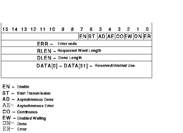
Figure 3-30 shows a PLC-5/250 Message Control structure.
Figure 3-25 shows a PLC-5/250 Timer structure.
Figure 3-25 shows a PLC-5/250 Timer structure.
Table 3-18 shows examples of legal Timer, Counter, Control, ASCII String, PID Control and Message Control data table addresses for the PLC-5/250.
Figure 3-24 PLC-5 / 250 Timer, Counter, Control, ASCII String, PID Control and Message Control Address Format
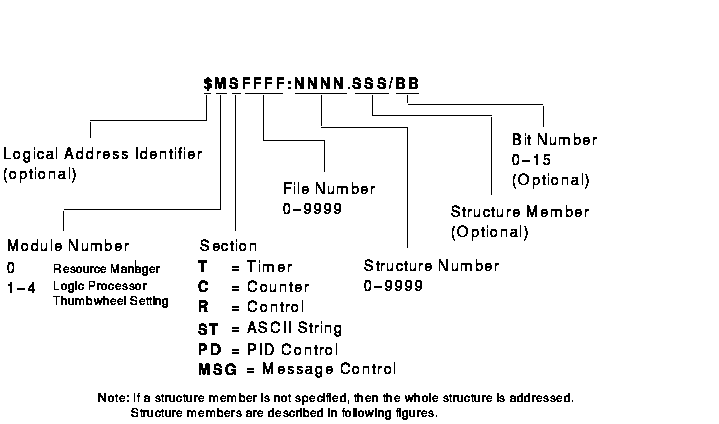
Figure 3-25 PLC-5 / 250 Timer Structure

Figure 3-26 PLC-5 / 250 Counter Structure
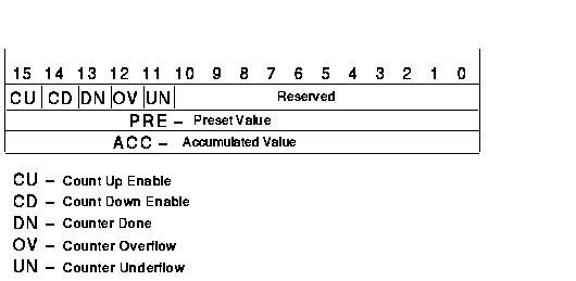
Figure 3-27 PLC-5 / 250 Control Structure
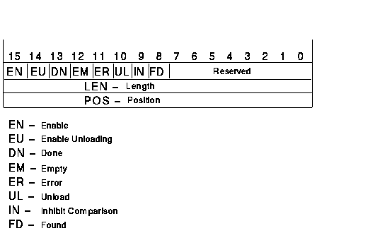
Figure 3-28 PLC-5 / 250 ASCII String Structure

Figure 3-29 PLC-5 / 250 PID Control Structure
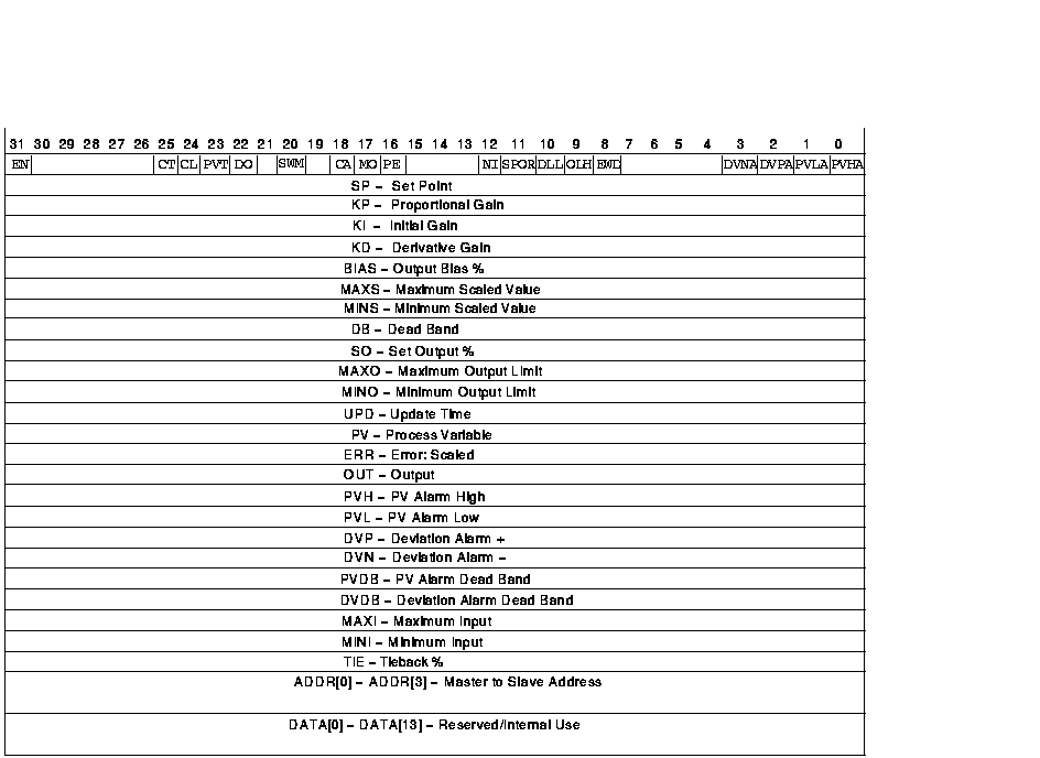
Figure 3-30 PLC-5 / 250 Message Control Structure
| Example Address | MMS Type1 | Description |
|---|---|---|
| $0T20:0.ACC | UNSIGNED_32 | Timer 0 in file 20 accumulated value |
| 0C91:3.PRE | INTEGER_16 | Counter 91 in file 3 preset value |
| 0T3:20.CTL/31 | BIT_STRING | Timer 20 in timer file 3 Enable bit 2 |
| 1R6:0.UL | BIT_STRING | Control 0 in file 6 unload bit 2 |
| 0T4:20.TD | BIT_STRING | Timer 20 in file 4 timer done bit 2 |
| 1R6:1.LEN | INTEGER_16 | Control 1 in control file 6 length value |
| 0ST16:0.LEN | INTEGER_16 | String 0 in file 16 length value |
| 0ST16:2 | VISIBLE_STRING 3 | String 2 in file 16 |
| 0ST16:3 | OCTET_STRING 3 | String 3 in file 16 |
| 0PD17:2.DVDB | FLOAT | PID Control 2 in file 17 Deviation Alarm Dead Band |
| 0PD17:2.EN | BIT_STRING | PID Control 2 in file 17 Enable |
| 0PD17:1.ADDR[0] | INTEGER_16 | PID Control 1 in file 17 Master-to-slave address 0 |
| 0MSG18:3.RLEN | INTEGER_16 | Message Control 3 in file 18 Requested Length |
| 1T0:5 |
Structure
4
UNSIGNED_16 UNSIGNED_32 UNSIGNED_32 |
All of timer 5 in file 0
Control Preset value Accumulated value |
| 0R8:10 |
Structure
4
UNSIGNED_16 INTEGER_16 INTEGER_16 |
All of control 10 in file 8
Control Length Position |
| 0PD17:0 |
Structure
4
UNSIGNED_32 FLOAT FLOAT FLOAT FLOAT FLOAT FLOAT FLOAT FLOAT FLOAT FLOAT FLOAT FLOAT FLOAT FLOAT FLOAT FLOAT FLOAT FLOAT FLOAT FLOAT FLOAT FLOAT FLOAT FLOAT Array of 4 UNSIGNED_16 Array of 14 FLOAT |
All of PID Control 0 in file 17
Control Set point Proportional gain Initial gain Derivative gain Output bias % Maximum scaled value Minimum scaled value Dead band Set output % Maximum output limit Minimum output limit Update time Process variable Error:scaled Output PV alarm high PV alarm low Deviation alarm + Deviation alarm - PV alarm dead band Deviation alarm dead band Maximum input Minimum intput Tieback % Master-to-slave address Reserved/internal use |
| 0MSG18:2 |
Structure
4
UNSIGNED_16 INTEGER_16 INTEGER_16 INTEGER_16 Array of 52 INTEGER_16 |
All of Message Control 2 in file 18
Control Error code Requested length Done length Reserved/internal use |
| Previous | Next | Contents | Index |