![[Compaq]](../../images/hp.gif)
![[Go to the documentation home page]](../../images/buttons/hp_bn_site_home.gif)
![[How to order documentation]](../../images/buttons/hp_bn_order_docs.gif)
![[Help on this site]](../../images/buttons/hp_bn_site_help.gif)
![[How to contact us]](../../images/buttons/hp_bn_comments.gif)
![[OpenVMS documentation]](../../images/hp_ovmsdoc_sec_head.gif)
| Document revision date: 15 July 2002 | |
![[Compaq]](../../images/hp.gif) |
![[Go to the documentation home page]](../../images/buttons/hp_bn_site_home.gif)
![[How to order documentation]](../../images/buttons/hp_bn_order_docs.gif)
![[Help on this site]](../../images/buttons/hp_bn_site_help.gif)
![[How to contact us]](../../images/buttons/hp_bn_comments.gif)
|
![[OpenVMS documentation]](../../images/hp_ovmsdoc_sec_head.gif)
|
|
| Previous | Contents | Index |
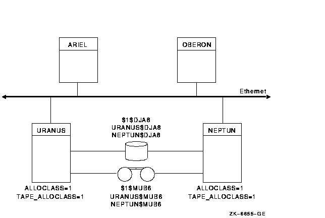
Figure 6-5 shows a DSA disk and tape that are dual pathed between two computers.
Figure 6-5 Disk and Tape Dual Pathed Between Computers

In this configuration:
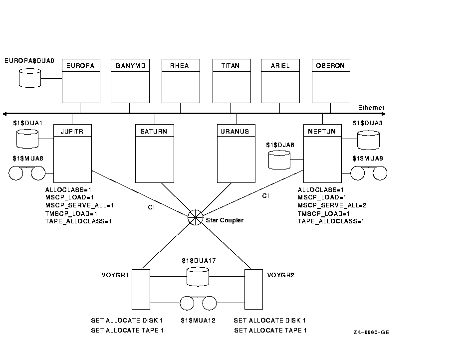
Figure 6-6 shows how device names are typically specified in a mixed-interconnect cluster. This figure also shows how relevant system parameter values are set for each CI computer.
Figure 6-6 Device Names in a Mixed-Interconnect Cluster

In this configuration:
Note: For optimal availability, two or more CI connected computers should serve HSC or HSJ devices to the cluster.
6.2.2.8 Node Allocation Classes and VAX 6000 Tapes
You must ensure that any tape drive is identified by a unique name that
includes a tape allocation class so that naming conflicts do not occur.
Duplicate names are more probable with VAX 6000 computers because TK console tape drives (located in the VAX 6000 cabinet) are usually named either MUA6 or MUB6. Thus, when you configure a VAXcluster system with more than one VAX 6000 computer, multiple TK console tape drives are likely to have the same name.
Specifying a Tape Allocation Class
To ensure that the TK console tape drives have names that are unique across the cluster, specify a tape allocation class name as a numeric value from 0 to 255, followed by the device name, as follows:
$tape-allocation-class$device-name |
Example:
Assume that $1$MUA6, $1$MUB6, $2$MUA6 are all unique device names. The first two have the same tape allocation class but have different controller letters (A and B, respectively). The third device has a different tape allocation class than the first two.
Consider the methods described in Table 6-3 to ensure a unique access path to VAX 6000 TK console tape drives.
| Method | Description | Comments |
|---|---|---|
| Set the TK console tape unit number to a unique value on each VAX 6000 system. | For VAXcluster systems in which tapes must be TMSCP served across the cluster, the tape controller letter and unit number of these tape drives must be unique clusterwide and must conform to the cluster device-naming conventions. If controller letters and unit numbers are unique clusterwide, the TAPE_ALLOCLASS system parameter can be set to the same value on multiple VAX 6000 systems. | The unit number of the TK console drives is controlled by the BI bus unit number plug of the TBK70 controller in the VAX 6000 BI backplane. A Compaq services technician should change the unit number so that it is unique from all other controller cards in the BI backplane. The unit numbers available are in the range of 0 to 15 (the default value is 6). |
| For VAXcluster systems configured with two or more VAX 6000 computers, set up the console tapes with different controller letters. | If your VAXcluster configuration contains only two VAX 6000 computers, contact a Compaq services technician to move the TBK70 controller card to another BI backplane within the same VAX computer. |
Moving the controller card changes the controller letter of the tape
drive without changing the unit number (for example, MUA6 becomes MUB6).
Note: The tape drives can have the same unit number. |
If you have RAID devices connected to StorageWorks RAID Array 210 or 230 subsystems, you might experience device-naming problems when running in a cluster environment if nonzero node allocation classes are used. In this case, the RAID devices will be named $n$DRcu, where n is the (nonzero) node allocation class, c is the controller letter, and u is the unit number.
If multiple nodes in the cluster have the same (nonzero) node allocation class and these same nodes have RAID controllers, then RAID devices that are distinct might be given the same name (for example, $1$DRA0). This problem can lead to data corruption.
To prevent such problems, use the DR_UNIT_BASE system parameter, which causes the DR devices to be numbered sequentially, starting with the DR_UNIT_BASE value that you specify. For example, if the node allocation class is $1, the controller letter is A, and you set DR_UNIT_BASE on one cluster member to 10, the first device name generated by the RAID controller will be $1$DRA10, followed by $1$DRA11, $1$DRA12, and so forth.
To ensure unique DR device names, set the DR_UNIT_BASE number on each
cluster member so that the resulting device numbers do not overlap. For
example, you can set DR_UNIT_BASE on three cluster members to 10, 20,
and 30 respectively. As long as each cluster member has 10 or fewer
devices, the DR device numbers will be unique.
6.2.3 Reasons for Using Port Allocation Classes
When the node allocation class is nonzero, it becomes the device name prefix for all attached devices, whether the devices are on a shared interconnect or not. To ensure unique names within a cluster, it is necessary for the ddcu part of the disk device name (for example, DKB0) to be unique within an allocation class, even if the device is on a private bus.
This constraint is relatively easy to overcome for DIGITAL Storage Architecture (DSA) devices, because a system manager can select from a large unit number space to ensure uniqueness. The constraint is more difficult to manage for other device types, such as SCSI devices whose controller letter and unit number are determined by the hardware configuration.
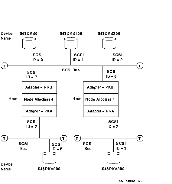
For example, in the configuration shown in Figure 6-7, each system has a private SCSI bus with adapter letter A. To obtain unique names, the unit numbers must be different. This constrains the configuration to a maximum of 8 devices on the two buses (or 16 if wide addressing can be used on one or more of the buses). This can result in empty StorageWorks drive bays and in a reduction of the system's maximum storage capacity.
Figure 6-7 SCSI Device Names Using a Node Allocation Class

The SCSI device name is determined in part by the SCSI controller through which the device is accessed (for example, B in DKBn). Therefore, to ensure that each node uses the same name for each device, all SCSI controllers attached to a shared SCSI bus must have the same OpenVMS device name. In Figure 6-7, each host is attached to the shared SCSI bus by controller PKB.
This requirement can make configuring a shared SCSI bus difficult, because a system manager has little or no control over the assignment of SCSI controller device names. It is particularly difficult to match controller letters on different system types when one or more of the systems have:
The port allocation class feature has two major benefits:
Using port allocation classes for naming SCSI, IDE, floppy disk, and PCI RAID controller devices removes the configuration constraints described in Section 6.2.2.9, in Section 6.2.3, and in Section 6.2.3.1. You do not need to use the DR_UNIT_BASE system parameter recommended in Section 6.2.2.9. Furthermore, each bus can be given its own unique allocation class value, so the ddcu part of the disk device name (for example, DKB0) does not need to be unique across buses. Moreover, controllers with different device names can be attached to the same bus, because the disk device names no longer depend on the controller letter.
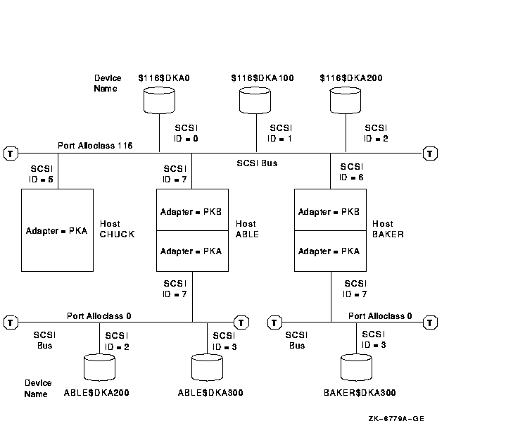
Figure 6-8 shows the same configuration as Figure 6-7, with two additions: a host named CHUCK and an additional disk attached to the lower left SCSI bus. Port allocation classes are used in the device names in this figure. A port allocation class of 116 is used for the SCSI interconnect that is shared, and port allocation class 0 is used for the SCSI interconnects that are not shared. By using port allocation classes in this configuration, you can do what was not allowed previously:
Figure 6-8 Device Names Using Port Allocation Classes

A port allocation class is a designation for all ports attached to a single interconnect. It replaces the node allocation class in the device name.
The three types of port allocation classes are:
Each type has its own naming rules.
6.2.4.1 Port Allocation Classes for Devices Attached to a Multi-Host Interconnect
The following rules pertain to port allocation classes for devices attached to a multihost interconnect:
Examples of device names that use this type of port allocation class are shown in Table 6-4.
| Device Name | Description |
|---|---|
| $101$DKA0 | The port allocation class is 101; DK represents the disk device category, A is the controller name, and 0 is the unit number. |
| $147$DKA0 | The port allocation class is 147; DK represents the disk device category, A is the controller name, and 0 is the unit number. |
The following rules pertain to port allocation class 0 for devices attached to a single-host interconnect:
Examples of device names that use port allocation class 0 are shown in Table 6-5.
| Device Name | Description |
|---|---|
| ABLE$DKD100 | ABLE is the name of the node to which the device is attached. D is the designation of the controller to which it is attached, not A as it is for port allocation classes with a nonzero class. The unit number of this device is 100. The port allocation class of $0$ is not included in the device name. |
| BAKER$DKC200 | BAKER is the name of the node to which the device is attached, C is the designation of the controller to which it is attached, and 200 is the unit number. The port allocation class of $0$ is not included in the device name. |
The designation of port allocation class -1 means that a port
allocation class is not being used. Instead, a node allocation class is
used. The controller letter remains its predefined designation. (It is
assigned by OpenVMS, based on the system configuration. It is not
affected by a node allocation class.)
6.2.4.4 How to Implement Port Allocation Classes
Port allocation classes were introduced in OpenVMS Alpha Version 7.1 with support in OpenVMS VAX. VAX computers can serve disks connected to Alpha systems that use port allocation classes in their names.
To implement port allocation classes, you must do the following:
Enabling the Use of Port Allocation Classes
To enable the use of port allocation classes, you must set a new SYSGEN parameter DEVICE_NAMING to 1. The default setting for this parameter is zero. In addition, the SCSSYSTEMIDH system parameter must be set to zero. Check to make sure that it is.
Assigning Port Allocation Classes
You can assign one or more port allocation classes with the OpenVMS Cluster configuration procedure, CLUSTER_CONFIG.COM (or CLUSTER_CONFIG_LAN.COM).
If it is not possible to use CLUSTER_CONFIG.COM or CLUSTER_CONFIG_LAN.COM to assign port allocation classes (for example, if you are booting a private system disk into an existing cluster), you can use the new SYSBOOT SET/CLASS command.
The following example shows how to use the new SYSBOOT SET/CLASS command to assign an existing port allocation class of 152 to port PKB.
SYSBOOT> SET/CLASS PKB 152 |
The SYSINIT process ensures that this new name is used in successive boots.
To deassign a port allocation class, enter the port name without a class number. For example:
SYSBOOT> SET/CLASS PKB |
The mapping of ports to allocation classes is stored in
SYS$SYSTEM:SYS$DEVICES.DAT, a standard text file. You use the
CLUSTER_CONFIG.COM (or CLUSTER_CONFIG_LAN.COM) command procedure or, in
special cases, SYSBOOT to change SYS$DEVICES.DAT.
6.2.4.5 Clusterwide Reboot Requirements for SCSI Interconnects
Changing a device's allocation class changes the device name. A clusterwide reboot ensures that all nodes see the device under its new name, which in turn means that the normal device and file locks remain consistent.
Rebooting an entire cluster when a device name changes is not mandatory. You may be able to reboot only the nodes that share the SCSI bus, as described in the following steps. The conditions under which you can do this and the results that follow are also described.
%MOUNT-F-VOLALRMNT, another volume of same label already mounted |
OpenVMS ensures that a node cannot boot if the result is a SCSI bus with naming different from another node already accessing the same bus. (This check is independent of the dismount check in step 1.) |
The MSCP server and the TMSCP server make locally connected disks and
tapes available to all cluster members. Locally connected disks and
tapes are not automatically cluster accessible. Access to these devices
is restricted to the local computer unless you explicitly set them up
as cluster accessible using the MSCP server for disks or the TMSCP
server for tapes.
6.3.1 Enabling Servers
To make a disk or tape accessible to all OpenVMS Cluster computers, the MSCP or TMSCP server must be:
| Parameter | Value | Meaning |
|---|---|---|
| MSCP_LOAD | 0 | Do not load the MSCP_SERVER. This is the default. |
| 1 | Load the MSCP server with attributes specified by the MSCP_SERVE_ALL parameter using the default CPU load capacity. | |
| >1 | Load the MSCP server with attributes specified by the MSCP_SERVE_ALL parameter. Use the MSCP_LOAD value as the CPU load capacity. | |
| TMSCP_LOAD | 0 | Do not load the TMSCP server and do not serve any tapes (default value). |
| 1 | Load the TMSCP server and serve all available tapes, including all local tapes and all multihost tapes with a matching TAPE_ALLOCLASS value. |
Table 6-7 summarizes the system parameter values you can specify for MSCP_SERVE_ALL and TMSCP_SERVE_ALL to configure the MSCP and TMSCP servers. Initial values are determined by your responses when you execute the installation or upgrade procedure or when you execute the CLUSTER_CONFIG.COM command procedure described in Chapter 8 to set up your configuration.
Starting with OpenVMS Version 7.2, the serving types are implemented as a bit mask. To specify the type of serving your system will perform, locate the type you want in Table 6-7 and specify its value. For some systems, you may want to specify two serving types, such as serving the system disk and serving locally attached disks. To specify such a combination, add the values of each type, and specify the sum.
In a mixed-version cluster that includes any systems running OpenVMS Version 7.1-x or earlier, serving all available disks is restricted to serving all disks whose allocation class matches the system's node allocation class (pre-Version 7.2 meaning). To specify this type of serving, use the value 9 (which sets bit 0 and bit 3). |
| Parameter | Bit | Value When Set | Meaning |
|---|---|---|---|
| MSCP_SERVE_ALL | 0 | 1 | Serve all available disks (locally attached and those connected to HS x and DSSI controllers). Disks with allocation classes that differ from the system's allocation class (set by the ALLOCLASS parameter) are also served if bit 3 is not set. |
| 1 | 2 | Serve locally attached (non-HS x and non-DSSI) disks. The server does not monitor its I/O traffic and does not participate in load balancing. | |
| 2 | 4 | Serve the system disk. This is the default setting. This setting is important when other nodes in the cluster rely on this system being able to serve its system disk. This setting prevents obscure contention problems that can occur when a system attempts to complete I/O to a remote system disk whose system has failed. | |
| 3 | 8 |
Restrict the serving specified by bit 0. All disks except those with
allocation classes that differ from the system's allocation class (set
by the ALLOCLASS parameter) are served.
This is pre-Version 7.2 behavior. If your cluster includes systems running Open 7.1- x or earlier, and you want to serve all available disks, you must specify 9, the result of setting this bit and bit 0. |
|
| TMSCP_SERVE_ALL | 0 | 1 | Serve all available tapes (locally attached and those connected to HS x and DSSI controllers). Tapes with allocation classes that differ from the system's allocation class (set by the ALLOCLASS parameter) are also served if bit 3 is not set. |
| 1 | 2 | Serve locally attached (non-HS x and non-DSSI) tapes. | |
| 3 | 8 |
Restrict the serving specified by bit 0. Serve all tapes except those
with allocation classes that differ from the system's allocation class
(set by the ALLOCLASS parameter).
This is pre-Version 7.2 behavior. If your cluster includes systems running OpenVMS Version 7.1- x or earlier, and you want to serve all available tapes, you must specify 9, the result of setting this bit and bit 0. |
Although the serving types are now implemented as a bit mask, the values of 0, 1, and 2, specified by bit 0 and bit 1, retain their original meanings. These values are shown in the following table:
| Value | Description |
|---|---|
| 0 | Do not serve any disks (tapes). This is the default. |
| 1 | Serve all available disks (tapes). |
| 2 | Serve only locally attached (non-HS x and non-DSSI) disks (tapes). |
| Previous | Next | Contents | Index |
![[Go to the documentation home page]](../../images/buttons/hp_bn_site_home.gif)
![[How to order documentation]](../../images/buttons/hp_bn_order_docs.gif)
![[Help on this site]](../../images/buttons/hp_bn_site_help.gif)
![[How to contact us]](../../images/buttons/hp_bn_comments.gif)
|
| privacy and legal statement | ||
| 4477PRO_010.HTML | ||