![[Compaq]](../../images/hp.gif)
![[Go to the documentation home page]](../../images/buttons/hp_bn_site_home.gif)
![[How to order documentation]](../../images/buttons/hp_bn_order_docs.gif)
![[Help on this site]](../../images/buttons/hp_bn_site_help.gif)
![[How to contact us]](../../images/buttons/hp_bn_comments.gif)
![[OpenVMS documentation]](../../images/hp_ovmsdoc_sec_head.gif)
| Document revision date: 15 July 2002 | |
![[Compaq]](../../images/hp.gif) |
![[Go to the documentation home page]](../../images/buttons/hp_bn_site_home.gif)
![[How to order documentation]](../../images/buttons/hp_bn_order_docs.gif)
![[Help on this site]](../../images/buttons/hp_bn_site_help.gif)
![[How to contact us]](../../images/buttons/hp_bn_comments.gif)
|
![[OpenVMS documentation]](../../images/hp_ovmsdoc_sec_head.gif)
|
|
| Previous | Contents | Index |
Systems running versions prior to Version 2.0 Availability Manager software collect and display information about LAN VC channel selection, but this information does not include managed objects, which were implemented beginning with Version 2.0 (Refer to the introduction to this chapter for more information about managed objects.)
Figure 4-12 is an example of a pre-Version 2.0 LAN VC Channel Selection Data page.
Figure 4-12 LAN VC Channel Selection Data Page (Pre-Version 2.0)
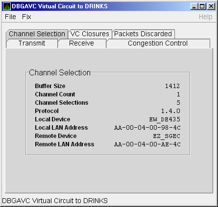
Table 4-12 describes the data displayed in Figure 4-12.
| Data | Description |
|---|---|
| Buffer Size | Maximum data buffer size for this virtual circuit. |
| Channel Count | Number of channels available for use by this virtual circuit. |
| Channel Selections | Number of channel selections performed. |
| Protocol | NISCA protocol version. |
| Local Device | Name of the local LAN device that the channel uses to send and receive packets. |
| Local LAN Address | Address of the local LAN device that performs sends and receives. |
| Remote Device | Name of the remote LAN device that the channel uses to send and receive packets. |
| Remote LAN Address | Address of the remote LAN device performing the sends and receives. |
Systems running Availability Manager Version 2.0 or later collect and display the following information about LAN VC Channel Selection. This information includes managed objects, which were implemented beginning with Version 2.0 (Refer to the introduction to this chapter for more information about managed objects.)
An additional requirement for displaying this data page is that managed objects be enabled on your system. Refer to postinstallation tasks described in the Installation Guide for OpenVMS Systems. |
Figure 4-13 is an example of a Channel Selection Data page on a Version 2.0 or later system.
Figure 4-13 LAN VC Channel Selection Data Page (Version 2.0 and Later)
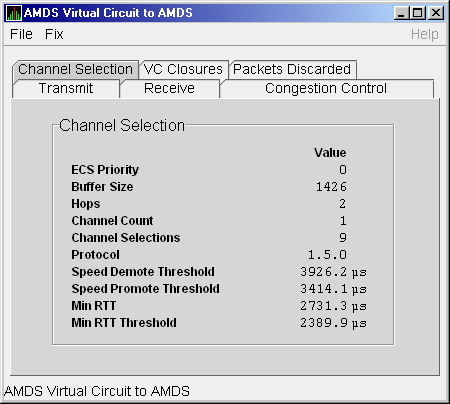
Table 4-13 describes the data displayed in Figure 4-13.
| Data | Description |
|---|---|
| ECS Priority | Current minimum priority a tight channel must have in order to be an ECS member. |
| Buffer Size | Maximum data buffer size for this virtual circuit. A channel must have this buffer size in order to be an ECS member. |
| Hops | Current minimum management hops a channel must have in order to be included in the ECS. |
| Channel Count | Number of channels currently available for use by this virtual circuit. |
| Channel Selections | Number of channel selections performed. |
| Protocol | Remote node's NISCA protocol version. |
| Speed Demote Threshold | Current threshold for reclassifying a FAST channel to SLOW. |
| Speed Promote Threshold | Current threshold for reclassifying a SLOW channel to FAST. |
| Min RTT | Current minimum average delay of any current ECS members. |
| Min RTT Threshold | Current threshold for reclassifying a channel as FASTER than the current set of ECS channels. |
LAN VC closures data is information about the number of times a virtual circuit has closed for a particular reason. Figure 4-14 is an example of a LAN VC Closures Data page.
Figure 4-14 LAN VC Closures Data Page
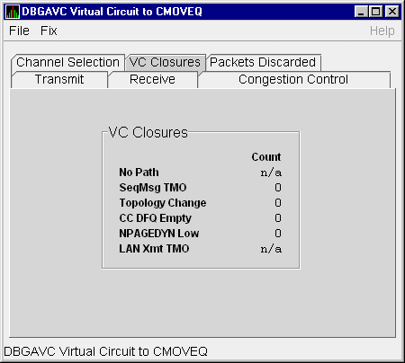
Table 4-14 describes the data displayed in Figure 4-14.
| Data | Description |
|---|---|
| No Path | Number of times the virtual circuit was closed because no usable LAN path was available. N/A on systems prior to Version 2.0. |
| SeqPkt TMO | Number of times the VC was closed because a sequenced packet's retransmit timeout count limit was exceeded. |
| Topology Change | Number of times the VC was closed because PEdriver performed a failover from a LAN path (or paths) with a large packet size to a LAN path with a smaller packet size. |
| CC DFQ Empty | Number of times the VC was closed because the channel control data-free queue (DFQ) was empty. |
| LAN XmtTMO | Number of times the VC was closed because a sequenced packet was not transmitted by the LAN device within an acceptable amount of time. |
| NPAGEDYN Low | Number of times the virtual circuit was lost because of a nonpaged pool allocation failure in the local node. |
LAN VC packets discarded data is information about the number of times packets were discarded for a particular reason. Figure 4-15 is an example of a LAN VC Packets Discarded Data page.
Figure 4-15 LAN VC Packets Discarded Data Page
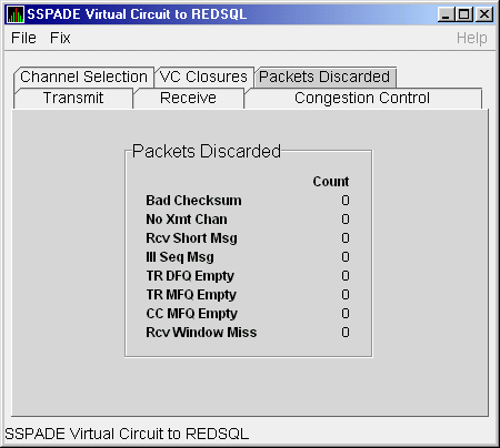
Table 4-15 describes the data displayed in Figure 4-15.
| Data | Description |
|---|---|
| Bad Checksum | Number of times there was a checksum failure on a received packet. |
| No Xmt Chan | Number of times no transmit channel was available. |
| Rcv Short Pkt | Number of times an undersized transport packet was received. |
| Ill Seq Pkt | Number of times an out-of-range sequence numbered packet was received. |
| TR DFQ Empty | Number of times the transmit data-free queue (DFQ) was empty. |
| TR MFQ Empty | Number of times the TR layer message-free queue (MFQ) was empty. |
| CC MFQ Empty | Number of times the channel control MFQ was empty. |
| Rcv Window Miss | Number of packets that could not be placed in the virtual circuit's receive cache because the cache was full. |
To display LAN channel details data, right-click a LAN channel summary data item on the Cluster Summary page (Figure 4-7). The Availability Manager displays a popup menu with the following options:
To display LAN channel details, select the Channel Details... item on
the menu. After a brief delay, a LAN Channel Overview Data Page, shown
in Figure 4-16, is displayed. A series of tabs at the top of the
Overview Data Page indicate additional channel pages you can display.
4.3.3.1 LAN Channel Overview Data Page
The LAN Channel Overview Data page, shown in Figure 4-16, displays general channel data.
Figure 4-16 LAN Channel Overview Data Page
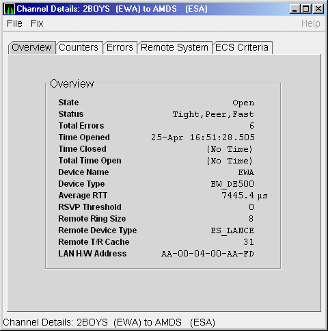
Table 4-16 describes the data displayed in Figure 4-16.
| Data | Description |
|---|---|
| State | Channel's current state: OPEN, PATH, or CLOSED. |
| Status | Channel status. |
| Total Errors | Sum of channel's error counters. |
| Time Opened | Last time that this channel had a path to a remote system. |
| Time Closed | Last time that this channel was closed. |
| Total Time Open | Total time that this channel has been open. |
| Device Name | Local LAN device name. |
| Device Type | Local LAN device type. |
| Average RTT | Average of measured round-trip time. |
| RSVP Threshold | Number of packets before requesting that the remote node immediately return an acknowledgment. |
| Remote Ring Size | Number of entries in the remote LAN device. |
| Remote Device Type | Remote LAN device type. |
| Remote T/R Cache | Number of out-of-order packets that the remote transmit/receive resequencing cache can buffer. |
| LAN H/W Address | LAN device's hardware address. |
The LAN Channel Counters Data page, shown in Figure 4-17, displays path counters data.
Figure 4-17 LAN Channel Counters Data Page
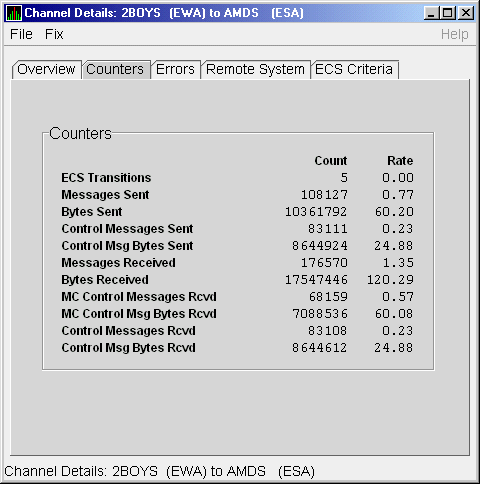
Table 4-17 describes the data displayed in Figure 4-17.
| Data | Description |
|---|---|
| ECS Transitions | Number of times this channel has been in and out of the equivalent channel set (ECS). |
| Messages Sent | Number of packets sent over this channel, including control packets. |
| Bytes Sent | Number of bytes transmitted on this channel, including control packets. |
| Control Messages Sent | Number of control packets sent, not including multicast packets. |
| Control Msg Bytes Sent | Number of control packet bytes sent, not including multicast packets. |
| Messages Received | Number of packets received by this channel. |
| Bytes Received | Number of bytes in packets received by this channel. |
| MC Control Messages Rcvd | Number of multicast control packets received. |
| MC Control Msg Bytes Rcvd | Number of multicast control packets bytes received. |
| Control Messages Rcvd | Number of control packets received. |
| Control Msg Bytes Rcvd | Number of control packet bytes received. |
The LAN Channel Errors Data page, shown in Figure 4-18, displays LAN channel errors data.
Figure 4-18 LAN Channel Errors Data Page
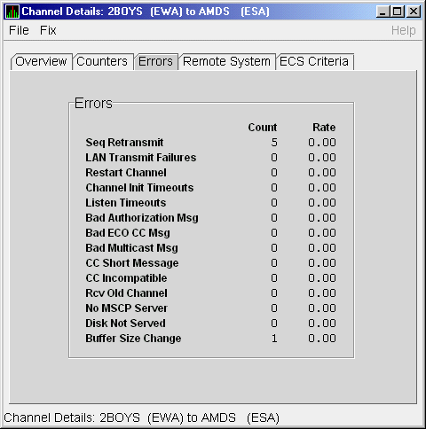
Table 4-18 describes the data displayed in Figure 4-18.
| Data | Description |
|---|---|
| Seq Retransmit | Number of times a sequenced VC packet sent on this channel was retransmitted, and the channel was penalized for the lost packet. |
| LAN Transmit Failures | Number of times the local LAN device reported a failure to transmit a packet, and channel was penalized for the lost packet. |
| Restart Channel | Close/restart because of channel control packet was received indicating the other end closed the channel and is restarting the channel handshake. |
| Channel Init Timeouts | Channel initialization handshake timeout. |
| Listen Timeouts | No packets of any kind, including HELLOs, were received in LISTEN_TIMEOUT seconds. |
| Bad Authorization Msg | Received a CC (channel control) packet with a bad authorization field. |
| Bad ECO CC Msg | Received a CC packet with an incompatible NISCA protocol ECO rev. field value. |
| Bad Multicast Msg | Received a bad multicast CC packet. |
| CC Short Packet | Received a CC packet that was too short. |
| CC Incompatible | Received a CC packet that was incompatible with existing channels for this virtual circuit. |
| Rcv Old Channel | Received a packet from an old instance of a channel. |
| No MSCP Server | No MSCP server available to respond to a received channel control solicit service packet asking this node to boot serve another node. |
| Disk Not Served | Disk is not served by this system. |
| Buffer Size Change | Change in buffer size. |
The LAN Channel Remote System Data page, shown in Figure 4-19, displays LAN path remote system data.
Figure 4-19 LAN Channel Remote System Data Page
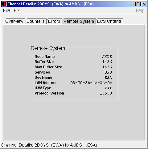
Table 4-19 describes the data displayed in Figure 4-19.
| Data | Description |
|---|---|
| Node Name | Node name of remote system. |
| Buffer Size | Buffer size (largest possible buffer size) of remote system. |
| Max Buffer Size | Current upper bound on buffer size usable on this channel. |
| Services | NISCA services supported on this channel. |
| Dev Name | Name of the remote LAN device. |
| LAN Address | Remote hardware address. |
| H/W Type | Hardware type of remote node. |
| Protocol Version | NISCA protocol version of remote system. |
The LAN Channel ECS Criteria Data page, shown in Figure 4-20, displays equivalent channel set criteria data.
Figure 4-20 LAN Channel ECS Criteria Data Page
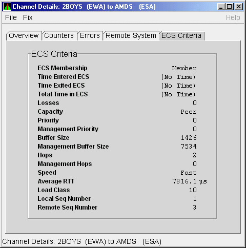
Table 4-20 describes the data displayed in Figure 4-20.
| Data | Description |
|---|---|
| ECS Membership | ECS membership status; that is, Member or Nonmember. |
| Time Entered ECS | Last time this channel entered the ECS. |
| Time Exited ECS | Last time this channel exited the ECS. |
| Total Time in ECS | Total time this channel was in the ECS. |
| Losses | Value representing channel's recent packet loss history. |
| Capacity | Channel's capacity rating based on evaluating its priority, buffer size, and hops values relative to the current ECS criteria. Values are: Ungraded, Peer, Inferior, Superior. |
| Priority | Channel's current priority for ECS calculations; it is the sum of the management priorities assigned to the local LAN device and to the channel. |
| Management Priority | Dynamic management-assigned priority. |
| Buffer Size | Negotiated maximum common buffer size: the smaller of local and remote BUS$ limits on block data field sizes. |
| Management Buffer Size | Maximum block data field size assigned by dynamic management. |
| Hops | Number of switches or bridges for this channel. |
| Management Hops | Management-supplied hops or media packet storage equivalent. |
| Speed | Classification of channel's delay relative to that of the lowest delay of any ECS member. |
| Average RTT | Average measured round-trip time. |
| Load Class | Lesser of the local and remote LAN device load class values. |
| Local Seq Number | Sequence number of the local channel. |
| Remote Seq Number | Sequence number of the remote channel. |
To display LAN adapters details data, right-click a LAN path (channel) summary data item on the Cluster Summary page (see Figure 4-6). The Availability Manager then displays a popup menu with the following options:
To display adapter details, select the Adapter Details... item on the menu. After a brief delay, a LAN Adapter Overview Data page (shown in Figure 4-21) is displayed.
A series of tabs at the top of the LAN Adapter Overview Data page indicate additional LAN adapter pages that you can display. Much of the LAN Adapter detail data corresponds to data displayed by the SCACP command SHOW LAN_DEVICE.
4.3.4.1 LAN Adapter Overview Data Page
The LAN Adapter Overview Data page, shown in Figure 4-21, displays
LAN adapters summary data.
Figure 4-21 LAN Adapter Overview Data Page
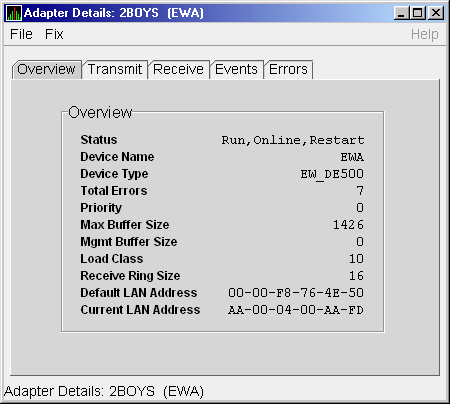
Table 4-21 describes the data displayed in Figure 4-21.
| Data | Description |
|---|---|
| Status | Device status: Run, Online, Restart; or Not in use by SCA. |
| Device Name | LAN adapter's device's name. |
| Device Type | OpenVMS device type value. |
| Total Errors | Total number of errors listed on the Errors page. |
| Priority | Dynamic management-assigned priority. |
| Max Buffer Size | Maximum data buffer size for this LAN device. |
| Mgmt Buffer Size | Dynamic management-assigned maximum block data field size. |
| Load Class | Load class. The rate in MBs currently being reported by the LAN device. |
| Receive Ring Size | Number of packets the LAN device can buffer before it discards incoming packets. |
| Default LAN Address | LAN device's hardware LAN address. |
| Current LAN Address | Current LAN address being used by this LAN device. |
| Previous | Next | Contents | Index |
![[Go to the documentation home page]](../../images/buttons/hp_bn_site_home.gif)
![[How to order documentation]](../../images/buttons/hp_bn_order_docs.gif)
![[Help on this site]](../../images/buttons/hp_bn_site_help.gif)
![[How to contact us]](../../images/buttons/hp_bn_comments.gif)
|
| privacy and legal statement | ||
| 6552PRO_007.HTML | ||