hp Reliable Transaction Router
System Manager's
Manual
2.13.4.4 Dual-Rail Setup
You may need to set up a dual-rail (multihome) environment to
accommodate a firewall, segregate a network subnet or possibly to ease
the load on an Ethernet line. In some situations, this can improve
performance.
For dual-rail
or multihome
setup, consider these topics:
- Physical network card setup
- RTR facility setup
- DNS (Domain Name System) support
- Tunnel configurations
Physical Network Card Setup
To set up frontends and routers in a dual-rail environment, use the
following steps:
- Install two network cards
in the dual-rail node. This can be your frontend or your router. The
two configurations are shown in Figure 2-3 and Figure 2-4.
- Assign each network card a unique IP address.
- Use static IP addresses for the network cards - check your
operating system installation documents for how to use the appropriate
utility or application to perform this setup.
- Create an RTR facility that spans all nodes. Specify the RTR Router
(TR) on the node with the two network cards, and use an * wildcard when
executing the Create Facility command on the router, (see the example
in RTR Facility Setup).
For example, the configuration shown in Figure 2-3 illustrates a
firewall
in a configuration with three RTR nodes and two network cards installed
on the router.
Figure 2-3 Dual-Rail Configuration with Network Cards on a
Router
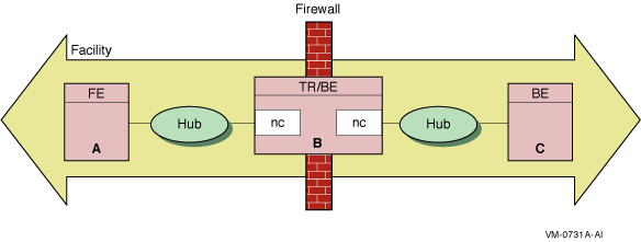
In Figure 2-3, Node A is a frontend, Node B, with the two network
cards (nc), is both a router and a backend, and Node C is a backend.
The hubs are Ethernet hubs. Figure 2-4 illustrates a frontend with
two network cards.
Figure 2-4 Dual-Rail Configuration with Network Cards on a
Frontend

RTR Facility Setup
To set up the dual-rail environment, you can, as an example, create
Facility A on three physical nodes (configuration shown in
Figure 2-3) with the following commands:
| Use this Create Facility command: |
On: |
|
RTR> CREATE FACILITY A /Frontend=A /Router=B
|
The frontend, node A.
|
|
RTR> CREATE FACILITY A /Router=B /Frontend=(A,*) /Backend=B
|
The router, node B.
|
|
RTR> CREATE FACILITY A /Router=B /Backend=C
|
The backend, node C.
|
Note
To ensure correct node recognition, include an explicit node name of a
known frontend with a wildcard.
|
RTR resolves addresses to one name in the DNS Server when you use a
wildcard for frontends from a router.
2.13.4.5 DNS Server Support
A host with more than one network interface is multihomed. In a
multihomed configuration, care must be taken to ensure that the
gethostbyname function returns the list of all possible network
addresses for the host. Otherwise, RTR may reject connections when it
cannot recognize the host. To return the address list, use a correctly
configured DNS. Using the /etc/hosts file on a UNIX server does not
return the list of addresses.
Networking support for machines with multiple network adapters
allows multiple IP connection targets for any host. With this
capability, any pair of machines connected by multiple network paths
can fail over to an alternate path if the primary path becomes unusable.
RTR determines the set of IP addresses to be used for a remote host
when the host name is looked up using the gethostbyname() API.
Depending on your platform and site policies, the IP address
information will be provided by UNIX hosts file entries, OpenVMS TCPIP
hosts entries, or by one or more BIND servers. Examples for a system
named 'host1' with two interfaces follow:
UNIX hosts file:
1.2.3.4    host1_interfaceb
1.2.4.4    host1 host1_interfaceb
|
OpenVMS:
TCPIP> set host "host1_interfaceb"/address=1.2.3.4
TCPIP> set host "host1"/address=1.2.4.4/alias="host1_interfaceb"
|
Given the information above, RTR will attempt to connect to remote
system 'host1' using address 1.2.4.4 first. Should this connection
attempt fail, RTR will retry using address 1.2.3.4.
Connection attempts that invoked address failover can be monitored
using the RTR monitor
picture Netstat.
Note that connection attempts using IP to unreachable hosts usually
terminate
with a timeout condition, but are often intercepted by the RTR
connection timeout whose default value is 60s. This is followed by a
further quiescent period whose default value is 90s. You may wish to
consider changing the values for these timers for a faster reconnection
rate.
2.13.4.6 Tunnel Configurations
If a tunnel separates the frontends from the routers, configure the
frontends on the routers with names corresponding to the pseudo-adapter
addresses assigned by the tunnel. If these are unpredictable, you can
use wildcards on the routers only.
If a tunnel separates the routers and the backends, configure each with
respect to the other with the name prefix "tunnel."
2.14 Running RTR as a Service on Windows NT
Once the RTR as Service has been installed (refer to the
Reliable Transaction Router Installation Guide), RTR can be started or stopped from the Control
Panel/Services panel using the START and STOP buttons provided.
- To start RTR, click on the START button.
- To stop RTR, click on the STOP button.
Note
Pressing START and STOP or the reverse in quick succession (within
approximately 5 seconds, depending on the speed of your computer) may
cause undesirable results because the Service executes quickly, making
available the other action button. However, the requested RTR action
may not have completed when the second action button is pressed. It is
therefore possible that the STOP action may be blocked by an incomplete
START action. Although the Service will claim to be stopped, RTR may in
fact remain started. Pressing whichever action button is functioning
should repair the problem.
|
By default, RTR will not restart automatically at system reboot. To
change this, set the Control Panel/Services entry for RTR.
2.14.1 Customizing the RTR Windows NT Service
When starting RTR, the Service looks for the file
usrstart.rtr
in the RTR home directory. When it finds the file, the Service executes
any RTR commands it may contain. RTR commands from
usrstart.rtr
execute after RTR has been started.
From the point of view of the Service, the RTR home directory is found
in the system-level environment variable
rtr_directory
, or, if that is not defined, then the directory from which the Service
was executed.
For the RTR Service to use it,
rtr_directory
must be defined in the system-level environment variables list, not the
user-level environment variables list. Also, the system must be
rebooted after the definition of
rtr_directory
is either created or changed for it to be used.
If a user-level copy of
rtr_directory
exists, it must identify the same RTR home directory as the
system-level copy, or if there is no system-level copy, the directory
containing the currently registered Service program. If it does not,
behavior of RTR is undefined.
Caution
Changing the value of
rtr_directory
, or reregistering the service from another directory while RTR is
running, is dangerous and should be avoided. Starting RTR from the
Service, then stopping it from DOS (or the reverse) should also be
avoided.
|
If you put STOP RTR in the
usrstart.rtr
file, it will stop RTR. The Service will not detect that RTR has been
stopped and will offer only the STOP action button. Pressing the STOP
button will fix the problem.
Similarly, when the Service stops RTR, it searches the RTR home
directory for the file
usrstop.rtr
and, if the file exists, it executes any RTR commands in it. User
commands from
usrstop.rtr
are executed before RTR has stopped.
Caution
If you put QUIT or EXIT in either
usrstart.rtr
or
usrstop.rtr
, RTR will exit improperly. As a result, an RTR command server process
incorrectly remains active, preventing the Service from starting or
stopping RTR, and preventing the RTR command server from exiting.
Because the RTR command server executes under the SYSTEM account, it
cannot be stopped from Task Manager other than by the SYSTEM account.
|
2.14.2 Files Created by the RTR Windows NT Service
If RTR is started from the Service rather than from a Command Prompt
window, several files are created in the RTR root directory.
-
srvcin.txt
is created to act as a command line input source
-
srvcout.txt
acts as a container for console output
-
rtrstart.rtr
contains the startup commands.
When the Service stops RTR, it recreates
srvcin.txt
and creates
rtrstop.rtr
for stopdown commands. Creation of these files is unconditional; that
is, they are created every time RTR is started or stopped, whether or
not they already exist. RTR will therefore ignore (and overwrite) any
changes made to one of these files.
2.15 Assignment of Processing States for Partitions
RTR assigns a primary or secondary processing state to a partition (or
a key-range definition), consisting of one or more server application
channels, which may or may not share a common process. On a given
backend, all such server application channels belonging to a given
partition will have the same processing state, but the processing state
for the same partition will normally be different on different
backends. The exception is the case of the standby processing state.
Because a given partition can have multiple standby backends, several
of these may be in a given state.
RTR determines the processing state of a given partition through the
use of a globally managed sequence number for that partition. By
default, the RTR router automatically assigns sequence numbers to
partitions during startup. When a server starts up on a backend and
declares a new partition for that backend, the partition initially has
a sequence number of zero. When the partition on that backend makes an
initial connection to the router, the router increases its sequence
number count for that partition by one and assigns the new sequence
number to the new backend partition. The active backend with the lowest
backend partition sequence number gets the primary processing state in
both shadow and standby configurations. That backend is also referred
to as the primary backend, though the same backend could have a standby
processing state for a different partition.
Under certain failover conditions, backend partitions may either retain
their original sequence number or be assigned a new sequence number by
the router. If a failure is caused by a network disruption, for
example, a backend partition retains its sequence number when it
reconnects with the router. However, if the backend node is rebooted or
RTR is restarted on the backend node, a new sequence number is assigned
by the router to any partitions
that start up on that backend. Routers will only assign new sequence
numbers to backend partitions that have a current sequence number of
zero, or if the backend partition is joining an existing facility and
has a sequence number that conflicts with that of another backend
partition on another node.
Sequence number information is obtained from the SHOW PARTITION/FULL
command. In the output of this command, the sequence number is
indicated by the "relative priority." Example 2-6 shows use
of the SHOW PARTITION/FULL command from a router partition. In this
example, the backend partition called Bronze has a sequence number of
1, and the backend partition called Gold has a sequence number of 2.
| Example 2-6 SHOW PARTITION/FULL for
Routers |
Router partitions on node SILVER in group "test" at Fri Nov 15 14:51:16 2002

Facility:                     Metals     State:                        ACTIVE
Low bound:                         0     High bound:               4294967295
Failover policy:                                              fail_to_standby
Backends:                                                         bronze,gold
 States:                                                      pri_act,sec_act
 Relative priorities:                                                     1,2
Primary main:                 bronze     Shadow main:                    gold
|
Example 2-7 shows the output of the SHOW PARTITION/FULL command for
each backend node.
| Example 2-7 SHOW PARTITION/FULL for
Backends |
Backend partitions on node BRONZE in group "test" at Mon Mar 22 14:52:32 1999


Partition name:                                                            p1

Configuration:-

Facility:                     Metals     State:                       pri_act
Low bound:                         0     High bound:               4294967295
Active servers:                    0     Free servers:                      1
Transaction presentation:     active     Last Rcvy BE:                   gold
Active transaction count:          0     Transactions recovered:            0
Failover policy:     fail_to_standby     Key range ID:               16777217
Master router:                silver     Relative priority:                 1
Recovery retry count:              0     Resource Manager:
Features:                                         Shadow,NoStandby,Concurrent

Backend partitions on node GOLD in group "test" at Mon Mar 22 14:54:12 1999

Partition name:                                                            p1

Configuration:-

Facility:                     Metals     State:                       sec_act
Low bound:                         0     High bound:               4294967295
Active servers:                    0     Free servers:                      1
Transaction presentation:     active     Last Rcvy BE:                 bronze
Active transaction count:          0     Transactions recovered:            0
Failover policy:     fail_to_standby     Key range ID:               16777216
Master router:                silver     Relative priority:                 2
Recovery retry count:              0     Resource Manager:
Features:                                         Shadow,NoStandby,Concurrent
|
2.15.1 Sequence Numbers in a Shadow Configuration
Figure 2-5 shows how sequence numbers are initially assigned in a
simple partition with two backends named Bronze and Gold, and a router
named Silver.
Figure 2-5 Assignment of Sequence Numbers in a Shadow
Configuration
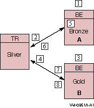
Table 2-3 Steps to Assigning Sequence Numbers
| Step |
Action |
|
1
|
A partition (with shadowing enabled) is started on backend Bronze.
|
|
2
|
The partition on Bronze obtains sequence number 1 from the router and
becomes the primary.
|
|
3
|
Another server on the same partition (with the same attributes) is
started on backend Gold.
|
|
4
|
The partition on backend Gold obtains sequence number 2 from the router
and becomes the secondary.
|
|
5
|
Backend Bronze crashes and reboots (the partition sequence number on
Bronze is reset to 0). The partition on backend Gold goes into Remember
mode.
|
|
6
|
When the server starts, the partition on backend Bronze obtains
sequence number 3 from the router and becomes the secondary; backend
Gold now becomes the primary.
|
|
7
|
The network connection from router Silver to backend Gold fails. The
partition on backend Bronze becomes the primary. The partition on
backend Gold loses quorum and is in a wait-for-quorum state.
|
|
8
|
The network connection to backend Gold is reestablished. The partition
on backend Gold retained its original sequence number of 2 and retains
the primary role while the partition on backend Bronze reassumes the
secondary role.
|
Alternatively, the roles of backend nodes can be specifically assigned
with the /PRIORITY_LIST qualifier to the SET PARTITION command. The
/PRIORITY_LIST qualifier can be used to ensure that when Bronze fails
and then returns to participate in the facility, it becomes the active
primary member. To ensure this, the following command would be issued
on both backend systems immediately after creating the partition:
SET PARTITION test/PRIORITY_LIST=(bronze,gold)
|
Use the same
priority list order on all partition members. If a different list is
used, the router will determine the sequence number for conflicting
members through the order in which those members joined the facility.
For example, if the above command were issued only on Bronze, and Gold
had the opposite priority list, the router would assign the lower
sequence number to the backend that joined the facility first.
2.15.2 Setting Failover Policy
Use the SET PARTITION command with the /FAILOVER_POLICY qualifier to
establish whether to fail over to a shadow or a standby backend. For
example, use the /FAILOVER_POLICY qualifier to select a new active
primary in configurations where shadowing is enabled. This qualifier
takes precedence over the /PRIORITY_LIST qualifier. Use the
/PRIORITY_LIST qualifier to determine the failover order for specific
nodes. It is most useful in cluster configurations where it can specify
the exact failover order for the nodes within the cluster.
For example, in a standby facility on a cluster of four nodes, the
/PRIORITY_LIST qualifier can specify the desired order of failover for
those cluster members. Some machines within a cluster may be more
powerful than other machines. This feature allows for the most
efficient use of those machines.
2.16 Router Selection in Facilities
Within a given facility, routers and backends connect to one another,
although nodes with a given role do not connect to nodes with the same
role, that is, routers do not connect to other routers. Frontends
connect to only one router at a given time. This selected router is
called the current router for that frontend in a facility.
A backend connects to all routers defined within a facility. The
connected router with the lowest network address is designated the
master router.
Internally, a node is identified through a structure called the Kernel
Net ID. The Kernel Net ID is a concatenation of all network addresses a
node is known as for all the protocols and interfaces that it supports.
The master router designation is only relevant to a backend. It is
where the backend goes to obtain and verify partition configuration and
facility information.
Routers are made known to the frontend systems through the list
specified in the /ROUTER=(list) qualifier to the CREATE FACILITY
command issued on the frontend or the router. This list specifically
determines the preferred router.
If the first router specified is not available, the next one on the
list is chosen. When the facility is created on the frontend, the list
of routers specified can be a subset of the routers contained within
the entire facility. Use this to prevent a frontend from selecting a
router reserved for other frontend systems.
Failback of routers to the preferred router is supported. Thus if the
preferred router is not available, but later becomes available, the
frontend automatically fails back and connects to its preferred router.
You can also use the /BALANCE qualifer with the CREATE or SET FACILITY
commands to randomize router selection. For more information on use of
the /BALANCE qualifer, see Section 2.8.
2.17 Clustering Considerations for RTR Standby Servers
The standby server remains idle while the RTR active server performs
its work, accepting transactions and updating the database. A failure
of the active RTR server occurs when either the process itself crashes,
when the RTRACP on the node crashes or when the node itself becomes
unreachable due to an operating or hardware fault, such as a network
interface failure. When the active server fails, the standby server
takes over, recovers any in-progress transactions, updates the
database, and communicates with clients until the active server returns.
There can be many concurrent instances of the active server, and
failover occurs only when the last remaining server has also failed.
There can be many instances of a standby server. Activation of the
standby server is transparent to the user. Standby failover behavior
depends on whether the standby and active nodes are members of the same
cluster and whether the cluster is a recognized or unrecognized cluster.
The clustering systems that RTR supports as recognized clusters are
OpenVMS clusters and Tru64 UNIX Clusters (TruClusters). RTR supports
Windows clusters as unrecognized clusters with file sharing. RTR treats
all other cluster systems (for example, Sun) as non-clustered.
Figure 2-6 shows a sample configuration of a clustered system.
Figure 2-6 Sample OpenVMS Cluster Running RTR
