![[Compaq]](../../images/compaq.gif)
![[Go to the documentation home page]](../../images/buttons/bn_site_home.gif)
![[How to order documentation]](../../images/buttons/bn_order_docs.gif)
![[Help on this site]](../../images/buttons/bn_site_help.gif)
![[How to contact us]](../../images/buttons/bn_comments.gif)
![[OpenVMS documentation]](../../images/ovmsdoc_sec_head.gif)
| Document revision date: 19 July 1999 | |
![[Compaq]](../../images/compaq.gif) |
![[Go to the documentation home page]](../../images/buttons/bn_site_home.gif)
![[How to order documentation]](../../images/buttons/bn_order_docs.gif)
![[Help on this site]](../../images/buttons/bn_site_help.gif)
![[How to contact us]](../../images/buttons/bn_comments.gif)
|
![[OpenVMS documentation]](../../images/ovmsdoc_sec_head.gif)
|
|
| Previous | Contents | Index |
A major benefit of OpenVMS is its support of a wide range of interconnects and protocols for network configurations and for OpenVMS Cluster System configurations. This chapter describes OpenVMS Alpha support for Fibre Channel as a storage interconnect for single systems and as a shared storage interconnect for multihost OpenVMS Cluster systems.
The following topics are discussed:
For information about multipath support for Fibre Channel configurations, see Chapter 6.
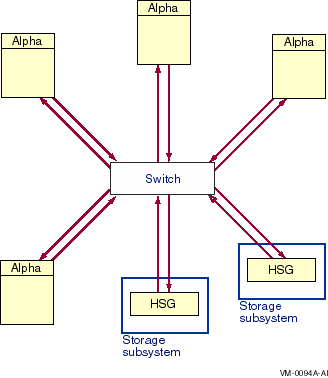
The Fibre Channel interconnect is shown generically in the figures in this chapter. It is represented as a horizontal line to which the node and storage subsystems are connected. Physically, the Fibre Channel interconnect is always radially wired from a switch, as shown in Figure 7-1. The representation of multiple SCSI disks and SCSI buses in a storage subsystem is also simplified. The multiple disks and SCSI buses, which one or more HSGx controllers serve as a logical unit to a host, are shown in the figures as a single logical unit. |
Fibre Channel is an ANSI standard network and storage interconnect that offers many advantages over other interconnects. Its most important features are described in Table 7-1.
| Feature | Description |
|---|---|
| High-speed transmission | 1.06 gigabits per second, full duplex, serial interconnect (can simultaneously transmit and receive 100 megabytes of data per second) |
| Choice of media | Initial OpenVMS support for fibre-optic media. Potential future support for copper media. |
| Long interconnect distances | Initial OpenVMS support for multimode fiber at 500 meters per link. Potential future support for 10 kilometer single-mode fiber links and 30 meter copper links. |
| Multiple protocols | Initial OpenVMS support for SCSI--3. Potential future support for IP, 802.3, HIPPI, ATM, IPI, and others. |
| Numerous topologies | Initial OpenVMS support for switched FC (highly scalable, multiple concurrent communications). Potential future support for fabric of switches and mixed arbitrated loop and switches |
The initial OpenVMS implementation supports a single-switch topology, with multimode fiber-optic media, at distances up to 500 meters per link.
Figure 7-1 shows a logical view of a switched topology. The FC nodes are either Alpha hosts, or storage subsystems. Each link from a node to the switch is a dedicated FC connection. The switch provides store-and-forward packet delivery between pairs of nodes. Concurrent communication between disjoint pairs of nodes is supported by the switch.
Figure 7-1 Switched Topology, Logical View

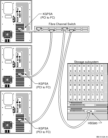
A physical view of a Fibre Channel switched topology is shown in Figure 7-2.
Figure 7-2 Switched Topology, Physical View

OpenVMS Alpha supports the Fibre Channel devices presented in Table 7-2. Fibre Channel configurations with other Fibre Channel equipment are not supported.
Note that Fibre Channel hardware names typically use the letter G to designate hardware that is specific to Fibre Channel.
| Component Name | Description | Minimum Version |
|---|---|---|
| AlphaServer 800, 1 1000A, 2 1200, 4000, 4100, 8200, 8400 3 | Alpha host. | OpenVMS Version 7.2 with DEC-AXPVMS-VMS72_HARDWARE-V0100--4.PCSI, 4 console rev. 5.4 |
| HSG80 | Fibre Channel controller module; 1 or 2 can be used in a Fibre Channel RAID storage cabinet. | Firmware rev. 8.4 |
| KGPSA-BC | OpenVMS Alpha PCI to multimode Fibre Channel host adapter. | Firmware rev. 2.20x1 |
| DSGGA-AA or -AB | 8-port or 16-port Fibre Channel switch. | Firmware rev. 1.6b |
| BNGBX- nn | Multimode fiber-optic cable ( nn denotes length in meters). | n/a |
Table 7-3 shows the initial configuration limits for Fibre Channel on OpenVMS, such as four Alpha hosts with four adapters each and two RAID storage cabinets per switch. These limits were determined by the testing that was possible before this first release, not by the software, hardware, or the Fibre Channel standards. OpenVMS plans to increase these limits in future releases.
| Component... | Supports... | Comments |
|---|---|---|
| Host | Up to four adapters, except for the AS800, which supports up to two adapters. | Each adapter must be connected to a different switch. Multipath access to storage as described in Chapter 6 is supported. |
| Switch |
Up to four hosts
Up to two RAID storage cabinets |
Each link from the switch connects directly to one host adapter or one HSG80 port. Connections from a switch to arbitrated loops, or to other switches, are not supported initially. |
| RAID storage cabinet | Connections to a maximum of two switches | Multiple connections to each switch are supported. Each storage cabinet can have one or two HSG80 controllers and up to 72 disk drives installed. |
| HSG80 storage controller | Disk devices only | HSG80 must be in SCSI-3 mode. |
| Host adapter (KGPSA) | Cannot be connected to the same PCI bus as the S3 Trio 64V+ Video Card (PB2GA-JC/JD) | On the AlphaServer 800, the integral S3 Trio must be disabled when the KGPSA is installed. |
| Operating system | All hosts on the Fibre Channel must run OpenVMS. | Hosts can be configured as a single cluster or as multiple clusters and/or nonclustered nodes. HSG80 access IDs must be used to ensure that each cluster and each non-clustered system has exclusive access to its storage devices. Each HSG storage device must be accessible to only one cluster or one non-clustered system. For information about HSG80 access IDs, refer to the HSG80 Array Controller ACS Version 8.4 Configuration and CLI Reference Guide. |
| HSG80 virtual disk units | All OpenVMS disk functions: system disk, dump disks, shadow set member, 1 quorum disk, and MSCP served disk | Each virtual disk must be assigned an identifier that is unique clusterwide. |
| Multimode fiber-optic media | 500 meters per link |
In addition to the configurations decribed in Table 7-3, OpenVMS
also supports the StorageWorks Data Replication Manager. This is a
remote data vaulting solution that enables the use of Fibre Channel
over longer distances.
7.2.1 Mixed-Version and Mixed-Architecture Cluster Support
Shared Fibre Channel OpenVMS Cluster storage is supported in both mixed-version and mixed-architecture OpenVMS Cluster systems. The following configuration requirements must be observed:
Figure 7-3 shows a single system using Fibre Channel as a storage interconnect.
Figure 7-3 Single System With Dual-Ported Storage Controllers

Note the following about this multipath configuration:
Figure 7-4 shows a multihost configuration with two independent Fibre Channel interconnects connecting the hosts to the storage subsystems.
Figure 7-4 Multihost Fibre Channel Configuration

Note the following about this configuration:
The storage subsystems shown in Figure 7-4 are connected to two switches, which is the limit allowed in the initial Fibre Channel release. If additional host adapters and switches are desired, they must connect to additional RAID storage cabinets, as shown in Figure 7-5.
Figure 7-5 shows the largest configuration that is supported for the initial release of Fibre Channel.
Figure 7-5 Largest Initially Supported Configuration

Note the following about this configuration:
Fibre Channel devices come with factory-assigned worldwide IDs (WWIDs).
These WWIDs are used by the system for automatic FC address assignment.
The FC WWIDs and addresses also provide the means for the system
manager to identify and locate devices in the FC configuration. The FC
WWIDs and adresses are displayed, for example, by the Alpha console and
by the HSG80 console. It is necessary, therefore, for the system
manager to understand the meaning of these identifiers and how they
relate to OpenVMS device names.
7.4.1 Fibre Channel Addresses and WWIDs
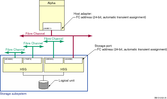
In most situations, Fibre Channel devices are configured to have temporary addresses. The device's address is assigned automatically each time the interconnect initializes. The device may receive a new address each time a Fibre Channel is reconfigured and reinitialized. This is done so that Fibre Channel devices do not require the use of address jumpers. There is one Fibre Channel address per port, as shown in Figure 7-6.
Figure 7-6 Fibre Channel Host and Port Addresses

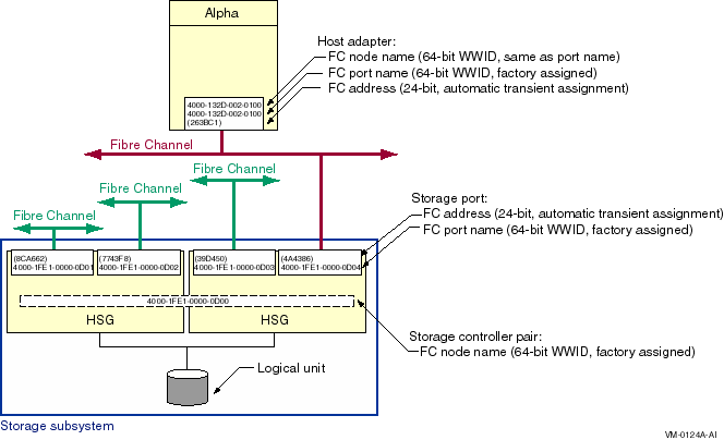
In order to provide more permanent identification, each port on each device has a WWID, which is assigned at the factory. Every Fibre Channel WWID is unique. Fibre Channel also has node WWIDs to identify multiported devices. WWIDs are used by the system to detect and recover from automatic address changes. They are useful to system managers for identifying and locating physical devices.
Figure 7-7 shows Fibre Channel components with their factory-assigned WWIDs and their Fibre Channel addresses.
Figure 7-7 Fibre Channel Host and Port WWIDs and Addresses

Note the following about this figure:
There is an OpenVMS name for each Fibre Channel storage adapter, for
each path from the storage adapter to the storage subsystem, and for
each storage device. These names are described in the following
sections.
7.4.2.1 Fibre Channel Storage Adapter Names
Fibre Channel storage adapter names, which are automatically assigned by OpenVMS, take the form FGx0:
The naming design places a limit of 26 adapters per system. (For the initial release, four adapters are supported per system.) This naming may be modified in future releases to support a larger number of adapters.
Fibre Channel adapters can run multiple protocols, such as SCSI and LAN. Each protocol is a pseudodevice associated with the adapter. For the initial implementation, just the SCSI protocol is supported. The SCSI pseudodevice name is PGx0, where x represents the same unit letter as the associated FGx0 adapter.
These names are illustrated in Figure 7-8.
Figure 7-8 Fibre Channel Initiator and Target Names

With the introduction of multipath SCSI support, as described in Chapter 6, it is necessary to identify specific paths from the host to the storage subsystem. This is done by concatenating the SCSI pseudodevice name, a decimal point (.), and the WWID of the storage subsystem port that is being accessed. For example, the Fibre Channel path shown in Figure 7-8 is named PGB0.4000-1FE1-0000-0D04.
Refer to Chapter 6 for more information on the display and use of
the Fibre Channel path name.
7.4.2.3 Fibre Channel Storage Device Identification
The four identifiers associated with each FC storage device are shown in Figure 7-9.
Figure 7-9 Fibre Channel Storage Device Naming

The logical unit number (LUN) is used by the system as the address of a specific device within the storage subsystem. This number is set and displayed from the HSG80 console by the system manager. It can also be displayed by the OpenVMS SDA utility.
Each Fibre Channel storage device also has a WWID to provide permanent, unique identification of the device. The HSG80 device WWID is 128 bits. Half of this identifier is the WWID of the HSG80 that created the logical storage device, and the other half is specific to the logical device. The device WWID is displayed by the HSG80 console and the AlphaServer console.
The third identifier associated with the storage device is a user-assigned device identifier. A device identifier has the following attributes:
The device identifier has a value of 567 in Figure 7-9. This value is used by OpenVMS to form the device name so it must be unique throughout the cluster. (It may be convenient to set the device identifier to the same value as the logical unit number (LUN). This is permitted as long as the device identifier is unique throughout the cluster.)
A Fibre Channel storage device name is formed by the operating system
from the constant $1$DGA and a device identifier,
nnnnn. The only variable part of the name is its
device identifier, which you assign at the HSG console. Figure 7-9
shows a storage device that is known to the host as $1$DGA567.
7.5 Using the AlphaServer Console for Configuring FC
The AlphaServer console can be used to view the status of an FC
interconnect. This allows you to confirm that the interconnect is set
up properly before booting. If you plan to use an FC device for booting
or dumping, you must perform some additional steps to set up those FC
devices at the console. These topics are discussed in the next sections.
7.5.1 Viewing the FC Configuration from the Console
Console SHOW commands can be used to display information about the devices that the console detected when it last probed the system's I/O adapters. Unlike other interconnects, however, FC devices are not automatically included in the SHOW DEVICE output. This is because FC devices are identified by their WWIDs, and WWIDs are too large to be included in the SHOW DEVICE output. Instead, the console provides a command for managing WWIDs, named the wwidmgr command. This command enables you to display information about FC devices and to define appropriate device names for the FC devices that will be used for booting and dumping.
Note the following points about using the wwidmgr command:
Refer to the Wwidmgr User's Manual for a complete description of the wwidmgr command.
The following examples, produced on an AlphaServer 4100 system, show some typical uses of the wwidmgr command. Other environments may require additional steps to be taken, and the output on other systems may vary slightly.
Note the following about Example 7-1:
| Example 7-1 Using wwidmgr -show wwid | |||
|---|---|---|---|
P00>>>set mode diag Console is in diagnostic mode P00>>>wwidmgr -show wwid polling kgpsa0 (KGPSA-B) slot 2, bus 0 PCI, hose 1 kgpsaa0.0.0.2.1 PGA0 WWN 1000-0000-c920-a7db polling kgpsa1 (KGPSA-B) slot 3, bus 0 PCI, hose 1 kgpsab0.0.0.3.1 PGB0 WWN 1000-0000-c920-a694 [0] UDID:10 WWID:01000010:6000-1fe1-0000-0d10-0009-8090-0677-0016 (ev:none) [1] UDID:50 WWID:01000010:6000-1fe1-0000-0d10-0009-8090-0677-0026 (ev:none) [2] UDID:51 WWID:01000010:6000-1fe1-0000-0d10-0009-8090-0677-0027 (ev:none) [3] UDID:60 WWID:01000010:6000-1fe1-0000-0d10-0009-8090-0677-0021 (ev:none) [4] UDID:61 WWID:01000010:6000-1fe1-0000-0d10-0009-8090-0677-0022 (ev:none) |
Example 7-2 shows how the wwidmgr show wwid -full command displays information about FC devices and how they are connected. The display has two parts:
| Example 7-2 Using wwidmgr -show wwid -full | |||
|---|---|---|---|
P00>>>wwidmgr -show wwid -full

kgpsaa0.0.0.2.1
- Port: 1000-0000-c920-a7db

kgpsaa0.0.0.2.1
- Port: 2007-0060-6900-075b

kgpsaa0.0.0.2.1
- Port: 20fc-0060-6900-075b

kgpsaa0.0.0.2.1
- Port: 5000-1fe1-0000-0d14
 - dga12274.13.0.2.1 WWID:01000010:6000-1fe1-0000-0d10-0009-8090-0677-0016
 - dga15346.13.0.2.1 WWID:01000010:6000-1fe1-0000-0d10-0009-8090-0677-0026
 - dga31539.13.0.2.1 WWID:01000010:6000-1fe1-0000-0d10-0009-8090-0677-0027
 - dga31155.13.0.2.1 WWID:01000010:6000-1fe1-0000-0d10-0009-8090-0677-0021
 - dga30963.13.0.2.1 WWID:01000010:6000-1fe1-0000-0d10-0009-8090-0677-0022

kgpsaa0.0.0.2.1
- Port: 5000-1fe1-0000-0d11
 - dga12274.14.0.2.1 WWID:01000010:6000-1fe1-0000-0d10-0009-8090-0677-0016
 - dga15346.14.0.2.1 WWID:01000010:6000-1fe1-0000-0d10-0009-8090-0677-0026
 - dga31539.14.0.2.1 WWID:01000010:6000-1fe1-0000-0d10-0009-8090-0677-0027
 - dga31155.14.0.2.1 WWID:01000010:6000-1fe1-0000-0d10-0009-8090-0677-0021
 - dga30963.14.0.2.1 WWID:01000010:6000-1fe1-0000-0d10-0009-8090-0677-0022

kgpsab0.0.0.3.1
- Port: 1000-0000-c920-a694

kgpsab0.0.0.3.1
- Port: 2007-0060-6900-09b8

kgpsab0.0.0.3.1
- Port: 20fc-0060-6900-09b8

kgpsab0.0.0.3.1
- Port: 5000-1fe1-0000-0d13
 - dgb12274.13.0.3.1 WWID:01000010:6000-1fe1-0000-0d10-0009-8090-0677-0016
 - dgb15346.13.0.3.1 WWID:01000010:6000-1fe1-0000-0d10-0009-8090-0677-0026
 - dgb31539.13.0.3.1 WWID:01000010:6000-1fe1-0000-0d10-0009-8090-0677-0027
 - dgb31155.13.0.3.1 WWID:01000010:6000-1fe1-0000-0d10-0009-8090-0677-0021
 - dgb30963.13.0.3.1 WWID:01000010:6000-1fe1-0000-0d10-0009-8090-0677-0022

kgpsab0.0.0.3.1
- Port: 5000-1fe1-0000-0d12
 - dgb12274.14.0.3.1 WWID:01000010:6000-1fe1-0000-0d10-0009-8090-0677-0016
 - dgb15346.14.0.3.1 WWID:01000010:6000-1fe1-0000-0d10-0009-8090-0677-0026
 - dgb31539.14.0.3.1 WWID:01000010:6000-1fe1-0000-0d10-0009-8090-0677-0027
 - dgb31155.14.0.3.1 WWID:01000010:6000-1fe1-0000-0d10-0009-8090-0677-0021
 - dgb30963.14.0.3.1 WWID:01000010:6000-1fe1-0000-0d10-0009-8090-0677-0022


[0] UDID:10 WWID:01000010:6000-1fe1-0000-0d10-0009-8090-0677-0016 (ev:none)
 - current_unit:12274 current_col: 0 default_unit:12274
          via adapter       via fc_nport       Con     DID     Lun
 -      kgpsaa0.0.0.2.1  5000-1fe1-0000-0d14   Yes   210013     10
 -      kgpsaa0.0.0.2.1  5000-1fe1-0000-0d11   No    210213     10
 -      kgpsab0.0.0.3.1  5000-1fe1-0000-0d13   Yes   210013     10
 -      kgpsab0.0.0.3.1  5000-1fe1-0000-0d12   No    210213     10

[1] UDID:50 WWID:01000010:6000-1fe1-0000-0d10-0009-8090-0677-0026 (ev:none)
 - current_unit:15346 current_col: 0 default_unit:15346
          via adapter       via fc_nport       Con     DID     Lun
 -      kgpsaa0.0.0.2.1  5000-1fe1-0000-0d14   Yes   210013     50
 -      kgpsaa0.0.0.2.1  5000-1fe1-0000-0d11   No    210213     50
 -      kgpsab0.0.0.3.1  5000-1fe1-0000-0d13   Yes   210013     50
 -      kgpsab0.0.0.3.1  5000-1fe1-0000-0d12   No    210213     50

[2] UDID:51 WWID:01000010:6000-1fe1-0000-0d10-0009-8090-0677-0027 (ev:none)
 - current_unit:31539 current_col: 0 default_unit:31539
          via adapter       via fc_nport       Con     DID     Lun
 -      kgpsaa0.0.0.2.1  5000-1fe1-0000-0d14   Yes   210013     51
 -      kgpsaa0.0.0.2.1  5000-1fe1-0000-0d11   No    210213     51
 -      kgpsab0.0.0.3.1  5000-1fe1-0000-0d13   Yes   210013     51
 -      kgpsab0.0.0.3.1  5000-1fe1-0000-0d12   No    210213     51

[3] UDID:60 WWID:01000010:6000-1fe1-0000-0d10-0009-8090-0677-0021 (ev:none)
 - current_unit:31155 current_col: 0 default_unit:31155
          via adapter       via fc_nport       Con     DID     Lun
 -      kgpsaa0.0.0.2.1  5000-1fe1-0000-0d14   Yes   210013     60
 -      kgpsaa0.0.0.2.1  5000-1fe1-0000-0d11   No    210213     60
 -      kgpsab0.0.0.3.1  5000-1fe1-0000-0d13   Yes   210013     60
 -      kgpsab0.0.0.3.1  5000-1fe1-0000-0d12   No    210213     60

[4] UDID:61 WWID:01000010:6000-1fe1-0000-0d10-0009-8090-0677-0022 (ev:none)
 - current_unit:30963 current_col: 0 default_unit:30963
          via adapter       via fc_nport       Con     DID     Lun
 -      kgpsaa0.0.0.2.1  5000-1fe1-0000-0d14   Yes   210013     61
 -      kgpsaa0.0.0.2.1  5000-1fe1-0000-0d11   No    210213     61
 -      kgpsab0.0.0.3.1  5000-1fe1-0000-0d13   Yes   210013     61
 -      kgpsab0.0.0.3.1  5000-1fe1-0000-0d12   No    210213     61
|
| Previous | Next | Contents | Index |
![[Go to the documentation home page]](../../images/buttons/bn_site_home.gif)
![[How to order documentation]](../../images/buttons/bn_order_docs.gif)
![[Help on this site]](../../images/buttons/bn_site_help.gif)
![[How to contact us]](../../images/buttons/bn_comments.gif)
|
| privacy and legal statement | ||
| 6318PRO_008.HTML | ||