![[Compaq]](../../images/compaq.gif)
![[Go to the documentation home page]](../../images/buttons/bn_site_home.gif)
![[How to order documentation]](../../images/buttons/bn_order_docs.gif)
![[Help on this site]](../../images/buttons/bn_site_help.gif)
![[How to contact us]](../../images/buttons/bn_comments.gif)
![[OpenVMS documentation]](../../images/ovmsdoc_sec_head.gif)
| Document revision date: 30 March 2001 | |
|
|
|
|
|
|
| Previous | Contents | Index |
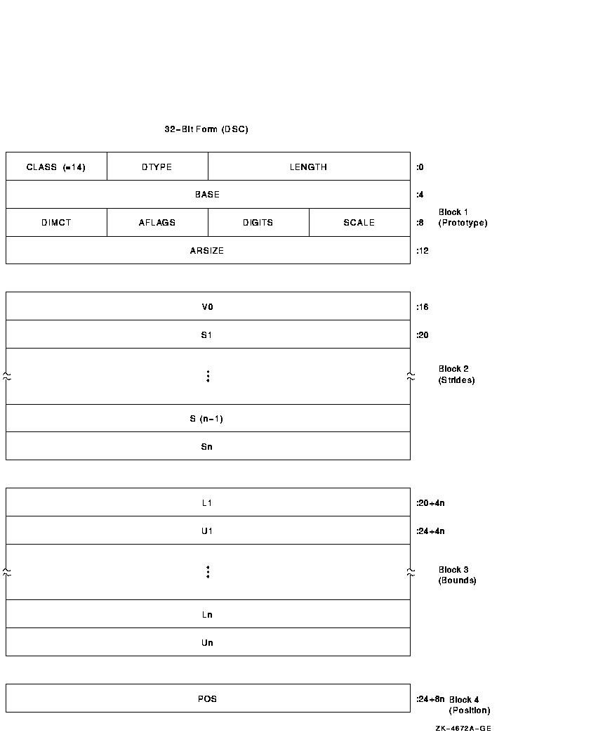
A variant of the noncontiguous array descriptor is used to specify an array of unaligned bit strings. Each array element is an unaligned bit string data type (DSC$K_DTYPE_VU) that starts and ends on an arbitrary bit boundary. The length of each element is the same and is 0 to 216 - 1 bits. You can access elements of the array directly by using the VAX variable bit field instructions. Therefore, the descriptor provides two components: a byte address, BASE, and a means to compute the signed bit offset, EB, with respect to BASE of an array element.
The unaligned bit array descriptor consists of four contiguous blocks that are always present. The first block contains the descriptor prototype information. Figure 5-12 shows the format of an unaligned bit array descriptor. Table 5-13 describes the fields of the descriptor.
Figure 5-12 Unaligned Bit Array Descriptor Format
| Symbol | Description | ||||||||
|---|---|---|---|---|---|---|---|---|---|
|
DSC$W_LENGTH
DSC64$Q_LENGTH |
Length of an array element in bits. | ||||||||
| DSC64$W_MBO | Must be 1. See Section 5.1. | ||||||||
|
DSC$B_DTYPE
DSC64$B_DTYPE |
A data-type code that must have the value 34, which specifies the unaligned bit string data type (see Sections 4.1 and 4.2). The use of other data types is reserved to Compaq. | ||||||||
|
DSC$B_CLASS
DSC64$B_CLASS |
Defines the descriptor class code that must be equal to 14 for CLASS_UBA. | ||||||||
|
DSC$A_BASE
DSC64$PQ_BASE |
Base address relative to the effective bit offset, EB, that is used to locate elements of the array. The base address need not be the first actual byte of data storage. | ||||||||
| DSC64$L_MBMO | Must be -1. See Section 5.1. | ||||||||
|
DSC$B_SCALE
DSC64$B_SCALE |
Reserved to Compaq. Must be 0. | ||||||||
|
DSC$B_DIGITS
DSC64$B_DIGITS |
If nonzero, the unsigned number of decimal digits in the internal representation. If 0, the number of digits can be computed based on LENGTH. This field should be 0 unless the TYPE field specifies a string data type that could contain numeric values. | ||||||||
|
DSC$B_AFLAGS
DSC64$B_AFLAGS |
Array flag bits <23:16>:
|
||||||||
|
DSC$B_DIMCT
DSC64$B_DIMCT |
Number of dimensions, n. | ||||||||
|
DSC$L_ARSIZE
DSC64$Q_ARSIZE |
If the elements are contiguous, ARSIZE is the total size of the array in bits. If the elements are not allocated contiguously or if the program unit allocating the descriptor is uncertain whether the array is actually contiguous, the value placed in ARSIZE might be meaningless. | ||||||||
|
DSC$L_V0
DSC64$Q_V0 |
Signed bit offset of element A(0,...,0) with respect to BASE. V 0 = POS - [S 1*L 1 + ... + S n *L n ]. | ||||||||
|
DSC$L_Si
DSC64$Q_Si |
Stride of the ith dimension. The difference between the bit (not byte) addresses of successive elements of the ith dimension. | ||||||||
|
DSC$L_L
i
DSC64$Q_L i |
Lower bound (signed) of the ith dimension. | ||||||||
|
DSC$L_U
i
DSC64$Q_U i |
Upper bound (signed) of the ith dimension. | ||||||||
|
DSC$L_POS
DSC64$Q_POS |
Relative bit position with respect to BASE of the first actual bit of the array, that is, element A(L 1,...,L n ). |
The following formulas specify the signed effective bit offset, EB, of an array element:
The signed effective bit offset, EB, of A(I1):
   EB = V0 + S1*I1
      = POS + S1*[I1 - L1]
|
The signed effective bit offset, EB, of A(I1,I2):
   EB = V0 + S1*I1 + S2*I2
      = POS + S1*[I1 - L1] + S2*[I2 - L2]
|
The signed effective bit offset, EB, of A(I1, ... , In):
   EB = V0 + S1*I1 + ... + Sn*In
      = POS + S1*[I1 - L1] + ... + Sn*[In - Ln]
|
Note that EB is computed ignoring integer overflow.
On VAX systems, EB is used as the position operand, and the content of BASE is used as the base address operand in the VAX variable-length bit field instructions. Therefore, BASE must specify a byte within 228 bytes of all bytes of storage in the bit array.
For example, consider a single-origin, one-dimensional, five-element array consisting of 3-bit elements allocated adjacently (therefore, S1 = 3). Assume BASE is byte 1000 and the first actual element, A(1), starts at bit <4> of byte 1001.
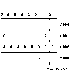
The following dependent field values occur in the descriptor:
POS = 12 V0 = 12 - 3*1 = 9 |
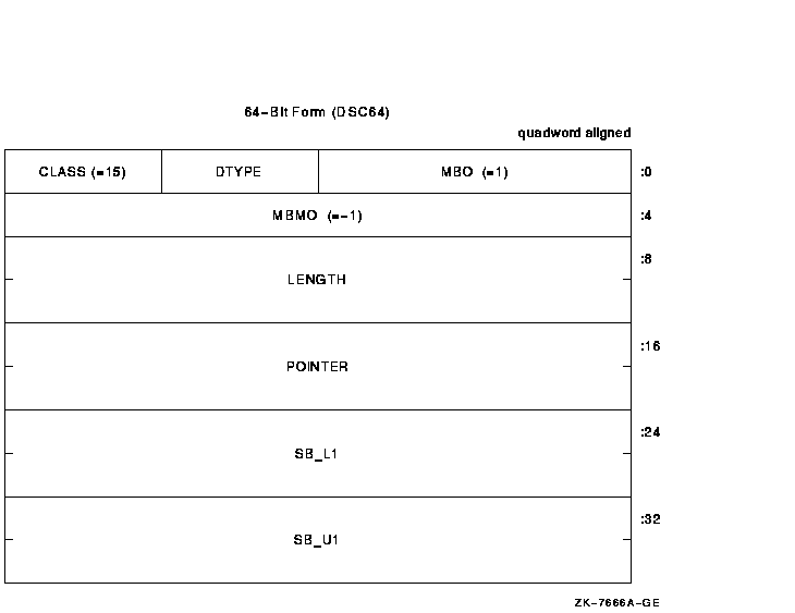
A variant of the fixed-length string descriptor is used to specify strings where the string is viewed as a one-dimensional array with user-specified bounds. Figure 5-13 shows the format of a string with bounds descriptor. Table 5-14 describes the fields of the descriptor.
Figure 5-13 String with Bounds Descriptor Format
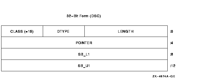
| Symbol | Description |
|---|---|
|
DSC$W_LENGTH
DSC64$Q_LENGTH |
Length of the string in bytes. |
| DSC64$W_MBO | Must be 1. See Section 5.1. |
|
DSC$B_DTYPE
DSC64$B_DTYPE |
A data-type code that must have the value 14, which specifies the character string data type (see Sections 4.1 and 4.2). The use of other data types is reserved to Compaq. |
|
DSC$B_CLASS
DSC64$B_CLASS |
Defines the descriptor class code that must be equal to 15 for CLASS_SB. |
|
DSC$A_POINTER
DSC64$PQ_POINTER |
Address of the first byte of data storage. |
| DSC64$L_MBMO | Must be -1. See Section 5.1. |
|
DSC$L_SB_L1
DSC64$Q_SB_L1 |
Lower bound (signed) of the first (and only) dimension. |
|
DSC$L_SB_U1
DSC64$Q_SB_U1 |
Upper bound (signed) of the first (and only) dimension. |
The following formula specifies the effective address, E, of a string element A(I):
E = POINTER + [I - SB_L1] |
If the string must be extended in a string comparison or assignment,
the space character (hexadecimal 20 if ASCII) is used as the fill
character.
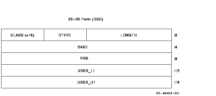
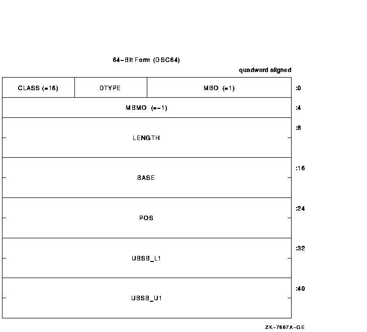
5.13 Unaligned Bit String with Bounds Descriptor (CLASS_UBSB)
A variant of the unaligned bit string descriptor is used to specify bit strings where the string is viewed as a one-dimensional bit array with user-specified bounds. Figure 5-14 shows the format of an unaligned bit string with bounds descriptor. Table 5-15 describes the fields of the descriptor.
Figure 5-14 Unaligned Bit String with Bounds Descriptor Format
| Symbol | Description |
|---|---|
|
DSC$W_LENGTH
DSC64$Q_LENGTH |
Length of the data item in bits. |
| DSC64$W_MBO | Must be 1. See Section 5.1. |
|
DSC$B_DTYPE
DSC64$B_DTYPE |
A data-type code that must have the value 34, which specifies the unaligned bit string data type (see Sections 4.1 and 4.2). The use of other data types is reserved to Compaq. |
|
DSC$B_CLASS
DSC64$B_CLASS |
Defines the descriptor class code that must be equal to 16 for CLASS_UBSB. |
|
DSC$A_BASE
DSC64$PQ_BASE |
Base address relative to the signed relative bit position, POS, used to locate the bit string. The base address need not be the first actual byte of data storage. |
| DSC64$L_MBMO | Must be -1. See Section 5.1. |
|
DSC$L_POS
DSC64$Q_POS |
Signed longword that defines the relative bit position of the first bit of the unaligned bit string to the BASE address. |
|
DSC$L_UBSB_L1
DSC64$Q_UBSB_L1 |
Lower bound (signed) of the first (and only) dimension. |
|
DSC$L_UBSB_U1
DSC64$Q_UBSB_U1 |
Upper bound (signed) of the first (and only) dimension. |
The following formula specifies the effective bit offset, EB, of a bit element A(I):
EB = POS + [I - UBSB_L1] |
All descriptor class codes from 0 through 191 not otherwise defined in this standard are reserved to Compaq. Classes 192 through 255 are reserved to Compaq's Computer Special Systems Group and customers.
Table 5-16 lists some specific descriptor classes and codes that are obsolete or reserved to Compaq.
| Descriptor | Code | Class |
|---|---|---|
| DSC$K_CLASS_V | 3 | Obsolete (variable buffer) |
| DSC$K_CLASS_PI | 6 | Obsolete (procedure incarnation) |
| DSC$K_CLASS_J | 7 | Reserved to DEBUG (label) |
| DSC$K_CLASS_JI | 8 | Obsolete (label incarnation) |
| DSC$K_CLASS_CT | 17 | Reserved to ACMS (compressed text) |
| DSC$K_CLASS_BFA | 191 | Reserved to BASIC (file array) |
Descriptor class codes 160 through 191 are reserved to Compaq for facility-specific purposes. These codes must not be passed between facilities, because different facilities might use the same code for different purposes. These codes can be used by compiler-generated code to pass parameters to the language-specific, run-time support procedures associated with that language or to the OpenVMS Debugger.
An OpenVMS condition is a hardware-generated synchronous exception or a software event that is to be processed in a manner similar to a VAX or an Alpha hardware exception.
Floating-point overflow exception, memory access violation exception, and reserved operation exception are examples of hardware-generated conditions. An output conversion error, an end of file, and the filling of an output buffer are examples of software events that might be treated as conditions.
Depending on the condition and on the program, you can exercise any of four types of action when a condition occurs:
When an unusual event or error occurs in a called procedure, the procedure can return a condition value to the caller indicating what has happened (see Section 6.1). The caller tests the condition value and takes the appropriate action.
When an exception is generated by the hardware, a branch out of the
program's flow of control occurs automatically. In this case, and for
certain software-generated events, it is more convenient to handle the
condition as soon as it is detected rather than to program explicit
tests.
6.1 Condition Values
Condition values are used in the OpenVMS operating system to provide the following functions:
A condition value is a longword that includes fields to describe the software component that generates the value, the reason the value was generated, and severity status of the condition value. Figure 6-1 shows the format of a condition value. Table 6-1 describes the fields of a condition value.
Figure 6-1 Format of a Condition Value
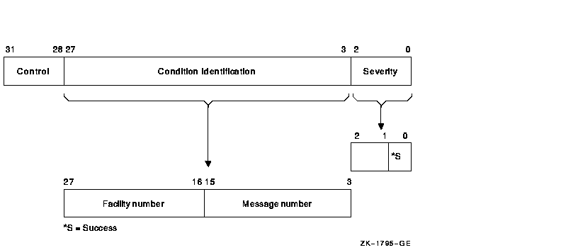
| Symbol | Description | |||||||||||||||||||||||||||
|---|---|---|---|---|---|---|---|---|---|---|---|---|---|---|---|---|---|---|---|---|---|---|---|---|---|---|---|---|
| Severity |
Indicates success or failure. The severity code bit <0> is set
for success (logical true) and is clear for failure (logical false);
bits <1> and <2> distinguish degrees of success or failure.
Bits <2:0>, when taken as an unsigned integer, are interpreted as
shown in the following table:
Section 6.1.1 more fully describes severity codes. |
|||||||||||||||||||||||||||
| Condition identification | Identifies the condition uniquely on a systemwide basis. | |||||||||||||||||||||||||||
| Message number | Describes the status, which can be a hardware exception that occurred or a software-defined value. Message numbers with bit <15> set are specific to a single facility. Message numbers with bit <15> clear are systemwide status codes. | |||||||||||||||||||||||||||
| Facility number | Identifies the software component generating the condition value. Bit <27> is set for customer facilities and is clear for Compaq facilities. | |||||||||||||||||||||||||||
| Control |
Controls the printing of the message associated with the condition
value. Bit <28> inhibits the message associated with the
condition value from being printed by the SYS$EXIT system service. This
bit is set by the system default handler after it has output an error
message using the SYS$PUTMSG system service. It should also be set in
the condition value returned by a procedure as a function value, if the
procedure has also signaled the condition (so the condition has been
printed or suppressed). Bits <31:29> must be 0; they are reserved
to Compaq for future use.
Table 6-2 lists the possible software symbols that are defined for the various fields of the condition-value longword. |
| Symbol | Value | Meaning | Field |
|---|---|---|---|
| STS$V_COND_ID | 3 | Position of 27:3 | Condition identification |
| STS$S_COND_ID | 25 | Size of 27:3 | Condition identification |
| STS$M_COND_ID | Mask | Mask for 27:3 | Condition identification |
| STS$V_INHIB_MSG | 1@28 | Position for 28 | Inhibit message on image exit |
| STS$S_INHIB_MSG | 1 | Size for 28 | Inhibit message on image exit |
| STS$M_INHIB_MSG | Mask | Mask for 28 | Inhibit message on image exit |
| STS$V_FAC_NO | 16 | Position of 27:16 | Facility number |
| STS$S_FAC_NO | 12 | Size of 27:16 | Facility number |
| STS$M_FAC_NO | Mask | Mask for 27:16 | Facility number |
| STS$V_CUST_DEF | 27 | Position for 27 | Customer facility |
| STS$S_CUST_DEF | 1 | Size for 27 | Customer facility |
| STS$M_CUST_DEF | 1@27 | Mask for 27 | Customer facility |
| STS$V_MSG_NO | 3 | Position of 15:3 | Message number |
| STS$S_MSG_NO | 13 | Size of 15:3 | Message number |
| STS$M_MSG_NO | Mask | Mask for 15:3 | Message number |
| STS$V_FAC_SP | 15 | Position of 15 | Facility-specific |
| STS$S_FAC_SP | 1 | Size for 15 | Facility-specific |
| STS$M_FAC_SP | 1@15 | Mask for 15 | Facility-specific |
| STS$V_CODE | 3 | Position of 14:3 | Message code |
| STS$S_CODE | 12 | Size of 14:3 | Message code |
| STS$M_CODE | Mask | Mask for 14:3 | Message code |
| STS$V_SEVERITY | 0 | Position of 2:0 | Severity |
| STS$S_SEVERITY | 3 | Size of 2:0 | Severity |
| STS$M_SEVERITY | 7 | Mask for 2:0 | Severity |
| STS$V_SUCCESS | 0 | Position of 0 | Success |
| STS$S_SUCCESS | 1 | Size of 0 | Success |
| STS$M_SUCCESS | 1 | Mask for 0 | Success |
| Previous | Next | Contents | Index |
|
|
| privacy and legal statement | ||
| 5973PRO_012.HTML | ||