![[Compaq]](../../images/compaq.gif)
![[Go to the documentation home page]](../../images/buttons/bn_site_home.gif)
![[How to order documentation]](../../images/buttons/bn_order_docs.gif)
![[Help on this site]](../../images/buttons/bn_site_help.gif)
![[How to contact us]](../../images/buttons/bn_comments.gif)
![[OpenVMS documentation]](../../images/ovmsdoc_sec_head.gif)
| Document revision date: 30 March 2001 | |
![[Compaq]](../../images/compaq.gif) |
![[Go to the documentation home page]](../../images/buttons/bn_site_home.gif)
![[How to order documentation]](../../images/buttons/bn_order_docs.gif)
![[Help on this site]](../../images/buttons/bn_site_help.gif)
![[How to contact us]](../../images/buttons/bn_comments.gif)
|
![[OpenVMS documentation]](../../images/ovmsdoc_sec_head.gif)
|
|
| Previous | Contents | Index |
An Ethernet address can be a physical address of a single node or a multicast address, depending on the value of the low-order bit of the first byte of the address (this bit is transmitted first). Following are the two types of node addresses:
Contrary to the Ethernet specification and the IEEE 802.3 Standard, the
broadcast address (FF-FF-FF-FF-FF-FF) must be enabled as a multicast
address in order to receive messages addressed to it.
9.9.3 Selecting an Ethernet Physical Address
The OpenVMS interface to the LAN controllers allows you to set a physical address of the controller. The selection of the physical address of a LAN controller is different for CSMA/CD (Ethernet and 802.3) and FDDI.
For CSMA/CD, all users of the controller must agree on this address. The first user of the controller chooses the physical address; any additional users of the controller must specify either the same physical address, no physical address, or change the address (if allowed). When all channels to the controller are shut down, the next user to start a channel chooses the physical address. The controller's physical address is always chosen on the first successful startup when there are no active ports. If the address is not chosen at this time, the controller's hardware address is used as the physical address.
For CSMA/CD, the Can Change Address parameter allows the physical address to be changed even though there are active users. If all current users of the controller have set the NMA$C_PCLI_CCA parameter to NMA$C_STATE_ON, then the physical address can be changed.
For FDDI, each port using a controller may specify its own unique
physical address. Any combination of sharing of physical addresses is
also allowed across the ports of an FDDI controller. For example, ports
A, B, and C may use one unique physical address and ports D and E may
use another unique address.
9.9.4 Ethernet Physical and Multicast Address Values
The following are multicast addresses assigned for use in cross-company communications:
| Value | Meaning |
|---|---|
| FF-FF-FF-FF-FF-FF | Broadcast |
| CF-00-00-00-00-00 | Loopback assistance |
The following are commonly used multicast addresses:
| Value | Meaning |
|---|---|
| AB-00-00-01-00-00 | Dump/load assistance |
| AB-00-00-02-00-00 | Remote console |
| AB-00-00-03-00-00 | Level 1 and Level 2 routers |
| AB-00-00-04-00-00 | All end nodes |
| 09-00-2B-02-00-00 | Level 2 routers |
|
AB-00-00-05-00-00
through AB-00-03-FF-FF-FF |
Reserved for future use |
| AB-00-03-00-00-00 | LAT |
|
AB-00-04-00-00-00
through AB-00-04-00-FF-FF |
For use by Compaq customers for their own applications |
|
AB-00-04-01-00-00
through AB-00-04-01-FF-FF |
Local area VMScluster |
|
AB-00-04-02-00-00
through AB-00-04-FF-FF-FF |
Reserved for future use |
| 09-00-2B-01-00-00 | Bridge management |
| 09-00-2B-01-00-01 | Bridge hello multicast |
Except for the global broadcast address (FF-FF-FF-FF-FF-FF), Token Ring hardware does not support the 802 standard group LAN address mechanism. Instead, it uses functional addresses. These functional addresses are locally administered group addresses (multicast addresses). The first two bytes of the address are always 03-00 (canonical format), and the remaining four bytes contain a bit mask that specifies which of the 32 possible combination masks is being described.
Because most OpenVMS LAN applications use standard multicast addresses, a mechanism has been designed to map functional addresses to globally and locally administered multicast addresses. This allows applications to use the same multicast addresses that are used in the other LAN media.
Table 9-6 shows the default mapping used by the OpenVMS Alpha Token Ring drivers:
| Multicast Address | Functional Address | Bit-Reversed | Description |
|---|---|---|---|
| 09-00-2B-00-00-04 | 03-00-00-00-02-00 | C0:00:00:00:40:00 | ISO 9542 All End-system Network Entites |
| 09-00-2B-00-00-05 | 03-00-00-00-01-00 | C0:00:00:00:80:00 | ISO 9542 All Intermediate System Network Entities |
| CF-00-00-00-00-00 | 03-00-00-08-00-00 | C0:00:00:10:00:00 | Loopback Assistance |
| AB-00-00-01-00-00 | 03-00-02-00-00-00 | C0:00:40:00:00:00 | MOP Dump/Load |
| AB-00-00-02-00-00 | 03-00-04-00-00-00 | C0:00:20:00:00:00 | MOP Remote Console |
| AB-00-00-03-00-00 | 03-00-08-00-00-00 | C0:00:10:00:00:00 | DNA L1 Routers |
| 09-00-2B-02-00-00 | 03-00-08-00-00-00 | C0:00:10:00:00:00 | DNA L2 Routers |
| 09-00-2B-02-01-0A | 03-00-08-00-00-00 | C0:00:10:00:00:00 | DECnet Phase IV---TRN---All Phase IV---TRN Routers |
| AB-00-00-04-00-00 | 03-00-10-00-00-00 | C0:00:08:00:00:00 | DNA End nodes |
| 09-00-2B-02-01-0B | 03-00-10-00-00-00 | C0:00:08:00:00:00 | Phase IV Prime Unknown |
| 09-00-2B-00-00-07 | 03-00-20-00-00-00 | C0:00:04:00:00:00 | PCSA NETBIOS Emulatn |
| 09-00-2B-00-00-0F | 03-00-40-00-00-00 | C0:00:02:00:00:00 | Local Area Transport (LAT) |
| 09-00-2B-02-01-04 | 03-00-80-00-00-00 | C0:00:01:00:00:00 | LAT Directory Service Solicit (to slave) |
| 09-00-2B-02-01-07 | 03-00-00-02-00-00 | C0:00:00:40:00:00 | LAT Directory Service Solicit---X Service Class |
| 09-00-2B-04-00-00 | 03-00-00-04-00-00 | C0:00:00:20:00:00 | LAST |
| 09-00-2B-02-01-00 | 03-00-00-00-08-00 | C0:00:00:00:10:00 | DNA Naming Service Advertisement |
| 09-00-2B-02-01-01 | 03-00-00-00-10-00 | C0:00:00:00:08:00 | DNA Naming Service Solicitation |
| 09-00-2B-02-01-02 | 03-00-00-00-20-00 | C0:00:00:00:04:00 | DNA Time Service |
| 03-00-00-00-00-01 | 03-00-00-00-00-01 | C0:00:00:00:00:80 | NETBUI Emulation |
If an application needs to change or add mappings, QIOs exist for performing such operations. If the system or network manager has a requirement regarding mapping of the functional addresses, the LAN control program (LANCP) utility may be used to manage the mapping. The following example maps the multicast address AB-01-01-01-02-03 to functional address 03-00-00-01-00-00 on Token Ring device ICA0:.
$MCR LANCP LANCP>SET DEVICE/MAP= - _LANCP>(MULTICAST=AB-01-01-01-02-03,- _LANCP>FUNCTIONAL=00-01-00-00) ICA0: |
Note that it is possible for more than one multicast address to map to
the same functional address. In all cases, the use of the functional
address is associated with an individual application's protocol.
9.10 Configuring ISA Devices (Alpha Only)
On Alpha systems, the way to configure an ISA LAN device is to type 'isacfg' at the console prompt (>>>). For complete information on using 'isacfg' from your console prompt, refer to the hardware documentation associated with your system for more information.
To help with your configuration, become familiar with the concepts listed in Table 9-7. Refer to your LAN hardware documentation for configuring information on how to set the jumper settings for those features in Table 9-7.
| Concept | Explanation |
|---|---|
| ISA Slot Number | Also called node. The ISA slot number of the device. Writing OpenVMS Alpha Device Drivers in C describes how to number ISA slots. |
| IRQ | Interrupt request line. Used to establish the interrupt level. Boards support IRQs between 1 and 15. Since OpenVMS does not support shared IRQs, every ISA device must have its own IRQ value reserved for it by the console ISACFG utility. |
| Port Address | I/O base control status registers (CSR) address. Boards usually have I/O addresses associated with their CSR locations. These locations must not be used by any other device on the system. |
| Memory Address | Also called shared memory. This address range is used to share memory resident on the adapter card between the host CPU and the LAN device on the adapter card. If the device uses shared memory, the I/O addresses for accessing this memory must be reserved. These locations must not be used by any other device on the system. |
| DMA Channel | If the device performs direct memory access (DMA), either slave or bus mastering, a DMA channel is required. Channels are numbered 1 through 7, but channel 4 is always reserved for the system. Refer to your adapter documentation for DMA channels supported by the device. |
The DE203, DE204, and DE205 Ethernet and DW110 Token Ring devices
require configuration using isacfg. The following information
and examples show how this is done.
9.10.1.1 DE203 Ethernet
The DE203 is a shared memory Ethernet device. Example 9-1 shows how to configure the OpenVMS software to use the DE203. The following example illustrates a configuration of:
| Example 9-1 Using the 'isacfg' at Console Prompt with the DE203 | |||
|---|---|---|---|
>>> isacfg -slot 1 -etyp 1 -ena 1 -irq0 5 -iobase0 %x300
           -membase0 %xd0000 -memlen0 %x1000 -handle "DE20" -mk
|
The command ("-mk") makes an isacfg entry for an ISA device at slot 1. It is a Single port type of device (-etyp 1). The -handle parameter tells the operating system what type of device it is.
The DE204 and DE205 are variants of the same adapter and are configured in the same way as the DE203. |
The DW110 is a bus mastering DMA device on the ISA bus. In addition to setting up the ISA I/O parameters, you may configure ring speed (4 or 16 Mbits) and media (UTP or STP). By using LANCP you can also configure ring speed and media during system startup. Example 9-2 shows how to configure the OpenVMS software to use the DW110. The following example illustrates a configuration of:
| Example 9-2 Using the 'isacfg' at Console Prompt with the DW110 | |||
|---|---|---|---|
>>> isacfg -slot 4 -etyp 1 -ena 1 -irq0 %xa -dmachan0 7
           -iobase0 %x4e20 -handle "DW11,STP,16" -mk
|
The command ("-mk") makes an isacfg entry for an ISA device at slot 4.
It is a Single port type of device (-etyp 1). The -handle parameter
tells the operating system that this is a DW110, that STP media is to
be used, and the ring speed is 16.
9.11 Configuring the Ethernet Media Type from the Console (Alpha Only)
On Alpha systems prior to OpenVMS Version 7.1, the SYS$EWDRIVER LAN device driver autosensed the media connection: BNC, AUI, or Twisted Pair. LAN adapters supported by this driver include the DE435, DE450, DE500, and Tulip integral Ethernet device. Their device name under OpenVMS is EWx0, where x is the controller letter.
With OpenVMS Version 7.1, this driver uses the setting of a console environment variable to select the proper media connection. For each EW device recognized by the console there is a console environment variable called EWx0_MODE, where x is the controller letter (e.g. A, B, C). The console environment variable is set with the command:
>>>SET EWx0_MODE media_selection |
In the previous command, the media_selection is one of the following:
Twisted-Pair
Full Duplex, Twisted-Pair
AUI
BNC
Fast
FastFD (Full Duplex)
Auto-Negotiate
During the OpenVMS device configuration a message is sent to the operator's console that shows which media was set by the console and handed to the device driver. For example, if the EWA0_MODE console environment variable was set to Fast the following message would be broadcast at the console:
%EWA0, Fast(100baseT) mode set by console |
If a console environment variable has been set with an unsupported media type for the corresponding device, then the driver attempts to autosense or auto negotiate the media type. Auto negotiation is supported by the DE500-AA.
An Alpha system console may assign a controller letter to an adapter
differently from OpenVMS. In this case, the letter designation in the
message broadcast to the console by the driver may not agree with the
console setting.
9.12 Frame Formats
Several different LAN physical layer protocols are supported by OpenVMS with some differences in frame formats. The following sections describe the similarities and differences in these frame formats. Despite differences, the QIO interface to the LAN drivers is designed to allow applications to run over the different media with few changes to the application.
The frame formats available in the LAN media are shown in Figure 9-3.
Figure 9-3 LAN Frame Formats
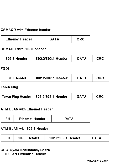
Note that CSMA/CD provides two frame formats and the FDDI provides one
frame format. The 802.1 header is an optional extension to the 802.2
header.
9.12.1 CSMA/CD Frames
There are two headers for CSMA/CD frames.
Figure 9-4 illustrates a CSMA/CD frame with an Ethernet header.
Figure 9-4 CSMA/CD Frame with Ethernet Header
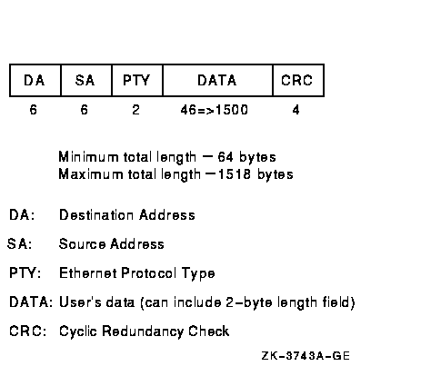
The Ethernet header consists of the DA, SA, and PTY fields. Ethernet frames must be at least 64 bytes in length, which means that the minimum data length is 46 bytes. Applications select Ethernet format by specifying NMA$C_LINFM_ETH (the default) as the value for NMA$C_PCLI_FMT in their P2 characteristics buffer. If the amount of actual data to be transmitted is less than 46 bytes, the CSMA/CD drivers transmit extra bytes of zero after the application data.
Figure 9-5 illustrates a CSMA/CD frame with an IEEE 802.3 header.
Figure 9-5 CSMA/CD Frame with IEEE 802.3 Header
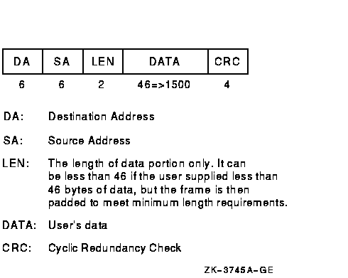
The IEEE 802.3 format is similar to the Ethernet format, except the PTY
field is replaced by the LEN field.
9.12.2 FDDI Frames
Figure 9-6 illustrates the format of FDDI frames.
Figure 9-6 FDDI Frame Format

The FDDI header consists of the FC, DA, and SA fields.
9.12.3 Token Ring Frames (Alpha Only)
Figure 9-7 illustrates the format of Token Ring frames.
Figure 9-7 Token Ring Frame Format (Alpha Only)
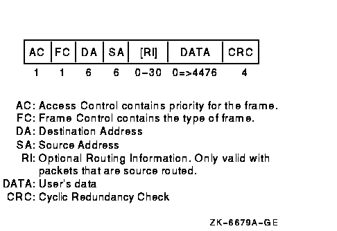
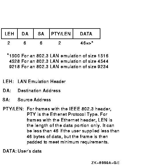
Figure 9-8 illustrates the format of LAN emulation data frame format for the IEEE 802.3 and Ethernet Header.
Figure 9-8 LAN Emulation Data Frame Format with IEEE 802.3/Ethernet Header
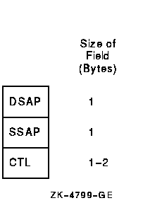
The 802.2 header follows the 802.3 header in a CSMA/CD frame and follows the FDDI header in an FDDI frame.
The 802.2 header is illustrated in Figure 9-9.
Figure 9-9 802.2 Header
This 802.2 header is followed by the 802.1 header illustrated in Figure 9-10 if the DSAP field is the SNAP SAP (AA hex), the SSAP field is the SNAP SAP, and the CTL field is UI (03 hex).
Figure 9-10 802.1 Header

The PID field consists of two subfields: the company portion of the PID and the implementation-specific portion of the PID (see Figure 9-11).
Figure 9-11 802.1 Header Subfields

Figure 9-12 details the field of the source routing header.
Figure 9-12 Source Routing Field (Alpha Only)
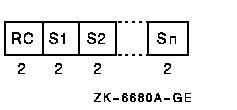
The routing control (RC) contains the information about how the packet is to be routed.
The Sn contains the segment identifier for the hop. Each segment
identifier contains a ring number and bridge number used in the hop.
9.13 Format Parameter
Each port (or user) of a LAN controller either specifies a value for the format characteristic of the port or assumes the default. The format characteristic has three valid values: Ethernet, 802, and 802E. This section describes the actual frame formats for each medium for each format parameter value.
For a format parameter value of NMA$C_LIMFM_ETH (the default), the frame formats are shown in Figure 9-13. Note that a name given to the FDDI frame with the Ethernet format is a mapped Ethernet frame.
Figure 9-13 Frames with Ethernet Format

For a format parameter value of NMA$C_PCLI_802, the frame formats are shown in Figure 9-14.
Figure 9-14 Frames with 802 Format
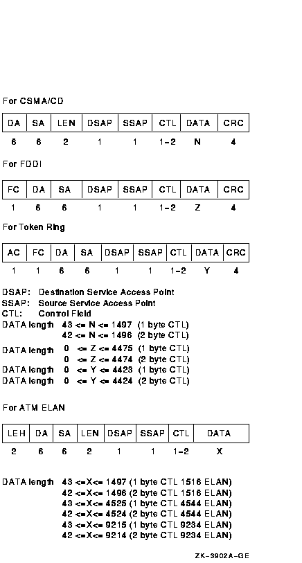
For a format parameter value of NMA$C_PCLI_802E, the frame formats are shown in Figure 9-15.
Figure 9-15 Frames with 802E Format

The Ethernet controllers can transmit and receive both Ethernet and 802.2/802.3 packets. Each port on a controller is able to transmit and receive either Ethernet or 802 packets. Ethernet and 802 ports can be assigned on the same controller at the same time.
The FDDI controllers can transmit and receive FDDI frames. There is a mapped Ethernet frame format that is comparable to the Ethernet packets sent and received by the Ethernet controllers.
At the time each port on the controller is started, one of three packet formats can be specified: Ethernet (default), standard 802 (referred to as 802 packet format), and extended 802. If no format is specified, the default format is used.
Each port on the controller must be unique on that controller. For each packet format, there is a parameter that distinguishes the port from all other ports with the same packet format. For Ethernet packet format ports, the 2-byte protocol type parameter defines the port. For 802 packet format ports, the 1-byte SAP defines the port. For extended 802 format ports, the 5-byte protocol identifier defines the port.
Sections 9.14.1, 9.14.2, and 9.14.3 describe the three packet formats and the characteristics unique to each format.
| Previous | Next | Contents | Index |
![[Go to the documentation home page]](../../images/buttons/bn_site_home.gif)
![[How to order documentation]](../../images/buttons/bn_order_docs.gif)
![[Help on this site]](../../images/buttons/bn_site_help.gif)
![[How to contact us]](../../images/buttons/bn_comments.gif)
|
| privacy and legal statement | ||
| 6136PRO_030.HTML | ||