![[Compaq]](../../images/compaq.gif)
![[Go to the documentation home page]](../../images/buttons/bn_site_home.gif)
![[How to order documentation]](../../images/buttons/bn_order_docs.gif)
![[Help on this site]](../../images/buttons/bn_site_help.gif)
![[How to contact us]](../../images/buttons/bn_comments.gif)
![[OpenVMS documentation]](../../images/ovmsdoc_sec_head.gif)
| Document revision date: 30 March 2001 | |
|
|
|
|
|
|
| Previous | Contents | Index |
It is sometimes useful to use the SYSGEN command SHOW to display the values of system parameters.
You do not need special privileges to invoke the SYSGEN utility. You can use either a qualifier or the name of a system parameter with the SHOW command, or you can use the SHOW/ALL command to display information about all system parameters. (Enter HELP SHOW at the SYSGEN> prompt for more information about the SHOW command.) The following example illustrates how you can check the current default, minimum, and maximum values for the SHADOWING parameter.
$ MCR SYSGEN SYSGEN> SHOW SHADOWING Parameter Name Current Default Minimum Maximum Unit Dynamic -------------- ------- ------- ------- ------- ---- ------- SHADOWING 2 0 0 3 Coded-value SYSGEN> |
When multiple nodes boot from a common system disk shadow set, ensure that all nodes specify a physical disk that is a source member of the system disk shadow set.
At boot time, the volume shadowing software attempts to construct a complete system disk shadow set based on the shadowing membership information contained in the storage control block (SCB) of the boot device. The SCB is an ODS-2 or ODS-5 file system data structure that resides on each storage device and contains information about shadow set membership (described in Section 6.1). Depending on what information is in the SCB at boot time, the following scenarios are possible:
The boot process automatically locates all the members of a system disk shadow set. You should not add system disk shadow set members in startup procedures as formerly recommended when phase I shadowing was supported.
Do not add members to a system disk shadow set in startup procedures. Doing so can result in loss of data under the following circumstances:
|
If the boot device fails, the following console warning message displays:
virtual-unit: does not contain the member named to VMB. System may not reboot. |
After the boot device has been repaired, manually add it back into the
system disk shadow set.
3.5 Booting Satellite Nodes from an MSCP Served System Disk Shadow Set
The OpenVMS operating system uses the Maintenance Operations Procedure (MOP) protocol to boot satellite nodes. The MOP protocol is provided by either the LANCP utility or by DECnet. The network software (LANCP or DECnet) must be configured on your system before you can use either LANCP or DECnet commands. You must also define a satellite's system disk using the LANCP or DECnet commands of the network software you are using for satellite booting. If the system disk is shadowed, the commands should specify the virtual unit or the virtual unit logical name rather than any physical unit.
The MOP server accesses the system disk shadow set (using the virtual unit defined) to perform downline load operations to the satellite. These operations include downline loading the physical boot device name to the satellite. When downline loading is complete, the satellite is able to connect to an MSCP server and access the physical boot device directly. The satellite's shadowing parameters are then used in the same way as a nonsatellite node.
You can use the SYS$MANAGER:CLUSTER_CONFIG_LAN.COM procedure or the SYS$MANAGER:CLUSTER_CONFIG.COM procedure to set MOP server, MSCP server, and satellite parameters automatically. When configuring satellite nodes with the cluster configuration command procedure, you can specify a shadowed system disk virtual unit as the satellite's system disk. The cluster configuration command procedure then automatically sets the satellite's system parameters SHADOW_SYS_DISK and SHADOW_SYS_UNIT for you. The values of these parameters are transferred automatically to the system parameter file VAXVMSSYS.PAR for VAX satellites and to ALPHAVMSSYS.PAR for Alpha satellites. (See the OpenVMS Cluster Systems manual for more information about using this command procedure.)
Example 3-3 shows the commands to enter to display the LANCP satellite database entries.
| Example 3-3 LANCP Database Example of a Satellite Node | |||
|---|---|---|---|
$ MCR LANCP LANCP> LIST DEVICE/MOPDLL Device Listing, permanent database: --- MOP Downline Load Service Characteristics --- Device State Access Mode Client Data Size ------ ----- ----------- ------ --------- ESA0 Disabled NoExlusive NoKnownClientsOnly 246 bytes FCA0 Disabled NoExlusive NoKnownClientsOnly 246 bytes LANCP> EXIT |
For DECnet--Plus commands, see the DECnet--Plus documentation.
Example 3-4 shows the NCP commands you should enter on a MOP server to display a satellite DECnet database entry. Note that the load assist parameter displays the shadow set virtual unit name that downline loads the satellite node HIWAY1. Example 3-4 uses an explicit virtual unit name. However, you might prefer to use a logical name that translates to the virtual unit.
| Example 3-4 DECnet Database Example of a Satellite Node | |||
|---|---|---|---|
$ MCR NCP NCP> SHOW NODE HIWAY1 CHAR Node Volatile Characteristics as of 12-MAR-2000 14:53:59 Remote node = 19.891 (HIWAY1) Hardware address = 03-03-03-03-03-BC Tertiary loader = SYS$SYSTEM:TERTIARY_VMB.EXE Load Assist Agent = SYS$SHARE:NISCS_LAA.EXE Load Assist Parameter = DSA1:<SYS4C.> NCP> EXIT |
You may need to adjust the settings of the SHADOW_MBR_TMO and SHADOW_MAX_COPY parameters on satellite nodes. These parameters are not automatically set by the cluster configuration command procedure. See Section 3.2 for more information.
The cluster configuration command procedure automatically enables shadowing on satellite nodes when you want to shadow the system disk. If you do not want to shadow the system disk but need to enable shadowing, you must do so manually after the cluster configuration command procedure completes. Set shadowing parameters in the satellite node's MODPARAMS.DAT file and execute AUTOGEN as described in Section 3.2 and in Section 3.3.1.
Figure 3-1 shows two satellite nodes with shadowed system disk volumes located in an OpenVMS Cluster system configuration. In this configuration, the devices $254$DUA1 and $254$DUA2 make up a two-member shadow set. The satellites HIWAY1 and BYWAY2 access shadow set members across the Ethernet via the MSCP servers in the two boot nodes.
Figure 3-1 Booting Satellite Nodes
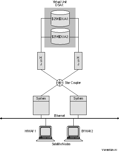
When a satellite node in Figure 3-1 is booted, the boot node (MOP server) downline loads initial bootstrap code from the virtual unit DSA1. The boot node points the satellite to use either $254$DUA1 or $254$DUA2 as a boot device for the remainder of the boot process. Note that the boot node must have the virtual unit mounted. The satellite then forms the system disk shadow set locally according to the shadow set membership information stored in the SCB on the boot device.
The following SHOW DEVICES command displays how the shadow set appears after the satellite node HIWAY1 is booted. In this example, the physical disk devices are accessed through the MSCP server node BTNODE.
$ SHOW DEVICES DSA1 Device Device Error Volume Free Trans Mnt Name Status Count Label Blocks Count Cnt DSA1: Mounted 0 MYVOLUME 181779 194 37 $254$DUA1: (BTNODE) ShadowSetMember 0 (member of DSA1:) $254$DUA2: (BTNODE) ShadowSetMember 0 (member of DSA1:) $ |
You can create, mount, and manage shadow sets interactively at the DCL command level, or in user-written programs:
This chapter describes how to create, mount, dismount, and dissolve shadow sets using interactive DCL commands. It also describes how to use the DCL command SET DEVICE to specify management attributes for shadow set members located at different sites in a multiple-site OpenVMS Cluster system. In addition, it describes how to use the DCL command SHOW DEVICE and the lexical function F$GETDVI to access current information about the state of shadow sets.
Volume Shadowing for OpenVMS improves data availability by ensuring that corresponding logical block numbers (LBNs) on multiple disk volumes contain the same information. Upon receiving a command to mount or dismount disks in a shadow set, the volume shadowing software may need to reconcile data differences and ensure that corresponding LBNs contain the same information.
An understanding of the copy and merge operations used for data
reconciliation is essential to the discussions in this chapter.
Therefore, you may find it helpful to refer to Chapter 6 to
understand how Volume Shadowing for OpenVMS ensures data availability
and consistency during changes in shadow set membership.
4.1 Allocating Devices
To avoid the possibility of another user mounting a particular device before you enter the MOUNT command, you can optionally allocate the device before issuing the MOUNT command. Use the DCL command ALLOCATE to provide your process with exclusive access to a physical device until you either deallocate the device or terminate your process. Optionally, you can associate a logical name with the device. The format for the ALLOCATE command is as follows:
|
ALLOCATE device-name[:] logical-name[:] |
To create a shadow set, you must use the MOUNT command with the /SHADOW qualifier to mount at least one physical disk into a shadow set and assign a virtual unit name to the set, as shown in Example 4-1.
| Example 4-1 Creating a Shadow Set | |||
|---|---|---|---|
$ MOUNT DSA23:(1) /SHADOW(2) =$4$DUA9:(3) volume-label(4) logical-name(5) |
This example forms a shadow set represented by the virtual unit DSA23, and includes one shadow set member, $4$DUA9.
In addition, you can specify /SYSTEM, /GROUP, or /CLUSTER to make the shadow set available to all users of a system, all members of a group, or all nodes in a cluster on which shadowing is enabled.
To create a three-member shadow set, you can add two members in a single MOUNT command to an existing one-member shadow set. This method optimizes the I/O operation because both members are copied at the same time. (See the example in Section 4.4.4.)
You can also streamline the process of creating a shadow set by initialized multiple devices in one command, using INITIALIZE/SHADOW/ERASE, as described in Section 4.3.
Upon receiving a command to create a shadow set, the volume shadowing
software may perform a copy or a merge operation to reconcile data
differences. If you are not sure which disks might be targets of copy
operations, you can specify the /CONFIRM or /NOCOPY qualifiers as a
precaution against overwriting important data when you mount a disk.
These and other MOUNT command qualifiers are discussed in Section 4.4.
4.3 Using INITIALIZE/SHADOW/ERASE to Streamline the Formation of a Shadow Set
You can use the DCL command INITIALIZE with the /SHADOW and /ERASE command qualifiers to initialize multiple members of a a future shadow set. Initializing multiple members in this way eliminates the requirement of a full copy when you later create a shadow set.
The INITIALIZE command with the /SHADOW and /ERASE qualifiers performs the following operations:
You can then mount up to three of the devices that you have initialized in this way as members of a new host-based shadow set.
Compaq strongly recommends that you use the /ERASE qualifier. By using the /ERASE qualifier, no merge operation is required when you create the shadow set with the MOUNT command.
All the devices must have identical, nonzero values for Total Blocks . You can view the Total Blocks value by entering the SHOW DEVICE/FULL command. If a device has never been mounted or initialized on this system, the SHOW DEVICE/FULL command for the device will not display a value for Total Blocks . To correct this condition, either mount and then dismount the device, or initialize the device. The Total Blocks value will then be displayed by SHOW DEVICE/FULL.
The use of INITIALIZE/SHADOW requires the VOLPRO privilege.
Note that the INITIALIZE/SHADOW command should not be used to initialize a disk to be added to an existing shadow set, since there is no benefit to be gained.
The format of this command follows:
INITIALIZE/SHADOW=(device_name1, device_name2, device_name3) label |
The following example shows correct use of this command. Note that the command specifies multiple devices on the same line.
$ INITIALIZE /ERASE /SHADOW=($4$MDA1300, $4$MDA1301) VOLATILE $ MOUN/SYS DSA42 /SHAD=( $4$MDA1300 , $4$MDA1301 ) VOLATILE %MOUNT-I-MOUNTED, VOLATILE MOUNTED ON _DSA42: %MOUNT-I-SHDWMEMSUCC, _$4$MDA1300: (WILD3) IS NOW A VALID MEMBER OF THE SHADOW SET %MOUNT-I-SHDWMEMSUCC, _$4$MDA1301: (WILD4) IS NOW A VALID MEMBER OF THE SHADOW SET $ SHO DEV DSA42: DEVICE DEVICE ERROR VOLUME FREE TRANS MNT NAME STATUS COUNT LABEL BLOCKS COUNT CNT DSA42: MOUNTED 0 VOLATILE 5799600 1 1 $4$MDA1300: (WILD3) SHADOWSETMEMBER 0 (MEMBER OF DSA42:) $4$MDA1301: (WILD4) SHADOWSETMEMBER 0 (MEMBER OF DSA42:) |
The following example shows incorrect use of this command. Do not use a separate command to initialize each device.
$ INITIALIZE /ERASE /SHADOW= $4$MDA1300 VOLATILE $ INITIALIZE /ERASE /SHADOW= $4$MDA1301 VOLATILE $ MOUN/SYS DSA42 /SHAD=( $4$MDA1300 , $4$MDA1301 ) VOLATILE %MOUNT-I-MOUNTED, VOLATILE MOUNTED ON _DSA42: %MOUNT-I-SHDWMEMSUCC, _$4$MDA1300: (WILD3) IS NOW A VALID MEMBER OF THE SHADOW SET %MOUNT-I-SHDWMEMSUCC, _$4$MDA1301: (WILD4) IS NOW A VALID MEMBER OF THE SHADOW SET $ SHO DEV DSA42: DEVICE DEVICE ERROR VOLUME FREE TRANS MNT NAME STATUS COUNT LABEL BLOCKS COUNT CNT DSA42: MOUNTED 0 VOLATILE 5799600 1 1 $4$MDA1300: (WILD3) ShadowSetMember 0 (member of DSA42:) $4$MDA1301: (WILD4) ShadowCopying 0 (copy trgt DSA42: 0% copied) |
If you omit the /ERASE qualifier, then the portions of the volume that do not contain file system data structures will contain indeterminate data. This data can differ from one shadow set member to another. Make sure to take this into account when using utilities that compare all of the LBNs between shadow set members.
The next time a full merge operation occurs, the presence of this
indeterminate data will cause the merge to take much longer than it
would have without use of the INITIALIZE/SHADOW/ERASE command. When
this full merge completes, the LBNs will contain identical data, and
the storage control block (SCB) will no longer indicate that the /ERASE
qualifier was omitted from the INITIALIZE/SHADOW command.
4.4 MOUNT Command Qualifiers for Shadowing
This section briefly describes the MOUNT command qualifiers that are useful for shadow set management. Refer also to the OpenVMS System Management Utilities Reference Manual for complete information about these and other DCL commands.
You must use the /SHADOW qualifier when you create a new shadow set or when you add a member to an existing shadow set. You can also use the optional qualifiers described in Table 4-1 and in Table 4-2. These qualifiers require the VOLPRO and OPER privileges, or your user identification code (UIC) must match the owner UIC of the volume being mounted. To mount a shadow set throughout the system, you must also have the SYSNAM privilege.
Detailed examples and descriptions of how to use these qualifiers are included in Section 4.5. In addition to the shadowing-specific qualifiers described in Table 4-1, the /NOASSIST, /SYSTEM, /GROUP, and /CLUSTER qualifiers are also frequently used when mounting shadow sets, as described in Table 4-2 and in Section 4.4.2.
| Previous | Next | Contents | Index |
|
|
| privacy and legal statement | ||
| 5423PRO_003.HTML | ||