Order Number: AA-RLE1A-TE
This document introduces Reliable Transaction Router and describes its concepts for the system manager, system administrator, and applications programmer.
Revision/Update Information: This is a new manual.
Software Version:
Reliable Transaction Router Version 4.0
Compaq Computer Corporation
Houston, Texas
© 2001 Compaq Computer Corporation
Compaq, the Compaq logo, AlphaServer, TruCluster, VAX, and VMS Registered in U. S. Patent and Trademark Office.
DECnet, OpenVMS, and PATHWORKS are trademarks of Compaq Information Technologies Group, L.P.
Microsoft and Windows NT are trademarks of Microsoft Corporation.
Intel is a trademark of Intel Corporation.
UNIX and The Open Group are trademarks of The Open Group.
All other product names mentioned herein may be trademarks or registered trademarks of their respective companies.
Confidential computer software. Valid license from Compaq required for possession, use, or copying. Consistent with FAR 12.211 and 12.212, Commercial Computer Software, Computer Software Documentation, and Technical Data for Commercial Items are licensed to the U.S. Government under vendor's standard commercial license.
Compaq shall not be liable for technical or editorial errors or omissions contained herein.
The information in this publication is subject to change without notice and is provided "AS IS" WITHOUT WARRANTY OF ANY KIND. THE ENTIRE RISK ARISING OUT OF THE USE OF THIS INFORMATION REMAINS WITH RECIPIENT. IN NO EVENT SHALL COMPAQ BE LIABLE FOR ANY DIRECT, CONSEQUENTIAL, INCIDENTAL, SPECIAL, PUNITIVE OR OTHER DAMAGES WHATSOEVER (INCLUDING WITHOUT LIMITATION, DAMAGES FOR LOSS OF BUSINESS PROFITS, BUSINESS INTERRUPTION OR LOSS OF BUSINESS INFORMATION), EVEN IF COMPAQ HAS BEEN ADVISED OF THE POSSIBILITY OF SUCH DAMAGES. THE FOREGOING SHALL APPLY REGARDLESS OF THE NEGLIGENCE OR OTHER FAULT OF EITHER PARTY AND REGARDLESS OF WHETHER SUCH LIABILITY SOUNDS IN CONTRACT, NEGLIGENCE, TORT OR ANY OTHER THEORY OF LEGAL LIABILITY, AND NOTWITHSTANDING ANY FAILURE OF ESSENTIAL PURPOSE OF ANY LIMITED REMEDY.
The limited warranties for Compaq products are exclusively set forth in the documentation accompanying such products. Nothing herein should be construed as constituting a further or additional warranty.
| Contents | Index |
The goal of this document is to assist an experienced system manager, system administrator, or application programmer to understand the Reliable Transaction Router (RTR) product.
This document contains the following chapters:
Additional resources in the RTR documentation kit include:
| Document | Content |
|---|---|
| For all users: | |
| Reliable Transaction Router Release Notes | Describes new features, changes, and known restrictions for RTR. |
| RTR Commands | Lists all RTR commands, their qualifiers and defaults. |
| For the system manager: | |
| Reliable Transaction Router Installation Guide | Describes how to install RTR on all supported platforms. |
| Reliable Transaction Router System Manager's Manual | Describes how to configure, manage, and monitor RTR. |
| Reliable Transaction Router Migration Guide | Explains how to migrate from RTR Version 2 to RTR Version 3 (OpenVMS only). |
| For the application programmer: | |
| Reliable Transaction Router Application Design Guide | Describes how to design application programs for use with RTR, illustrated with both the C and C++ interfaces. |
| Reliable Transaction Router C++ Foundation Classes | Describes the object-oriented C++ interface that can be used to implement RTR object-oriented applications. |
| Reliable Transaction Router C Application Programmer's Reference Manual | Explains how to design and code RTR applications using the C programming language; contains full descriptions of the basic RTR API calls. |
You can find additional information on RTR and existing implementations on the RTR web site at http://www.compaq.com/rtr/.
Compaq welcomes your comments on this guide. Please send your comments and suggestions by email to rtrdoc@compaq.com. Please include the document title, date from title page, order number, section and page numbers in your message. For product information, send email to rtr@compaq.com.
This manual adopts the following conventions:
| Convention | Description |
|---|---|
| New term | New terms are shown in bold when introduced and defined. All RTR terms are defined in the glossary at the end of this document or in the supplemental glossary in the RTR Application Design Guide. |
| User input | User input and programming examples are shown in a monospaced font. Boldface monospaced font indicates user input. |
| Terms and titles | Terms defined only in the glossary are shown in italics when presented for the first time. Italics are also used for titles of manuals and books, and for emphasis. |
| FE | RTR frontend |
| TR | RTR transaction router or router |
| BE | RTR backend |
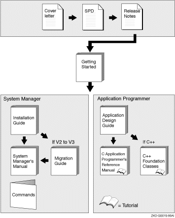
The reading path to follow when using the Reliable Transaction Router information set is shown in Figure 1.
Figure 1 RTR Reading Path
This document introduces RTR and describes RTR concepts. It is intended for the system manager or administrator and for the application programmer who is developing an application that works with Reliable Transaction Router (RTR).
Reliable Transaction Router (RTR) is failure-tolerant transactional messaging middleware used to implement large, distributed applications with client/server technologies. RTR helps ensure business continuity across multivendor systems and helps maximize uptime.
Interoperability
You use the architecture of RTR to ensure high availability and transaction completion. RTR supports applications that run on different hardware and different operating systems. RTR also works with several database products including Oracle, Microsoft Access, Microsoft SQL Server, Sybase, and Informix. For specifics on operating systems, operating system versions, and supported hardware, see the Reliable Transaction Router Software Product Description for each supported operating system.
Networking
RTR can be deployed in a local or wide area network and can use either TCP/IP or DECnet for its underlying network transport.
RTR provides a continuous computing environment that is particularly valuable in financial transactions, for example in banking, stock trading, or passenger reservations systems. RTR satisfies many requirements of a continuous computing environment:
RTR additionally provides the following capabilities, essential in the demanding transaction processing environment:
RTR also ensures that transactions have the ACID properties. A transaction with the ACID properties has the following attributes:
For more details on transactional ACID properties, see the discussion later in this document, and in the RTR Application Design Guide.
The following terms are either unique to RTR or redefined when used in the RTR context. If you have learned any of these terms in other contexts, take the time to assimilate their meaning in the RTR environment. The terms are described in the following order:
RTR Application
An RTR application is user-written software that executes within the confines of several distributed processes. The RTR application may perform user interface, business, and server logic tasks and is written in response to some business need. An RTR application can be written in any language, commonly C or C++, and includes calls to RTR. RTR applications are composed of two kinds of actors, client applications and server applications. An application process is shown in diagrams as an oval, open for a client application, filled for a server application.
Client
A client is always a client application, one that initiates and demarcates a piece of work. In the context of RTR, a client must run on a node defined to have the frontend role. Clients typically deal with presentation services, handling forms input, screens, and so on. A client could connect to a browser running a browser applet or be a webserver acting as a gateway. In other contexts, a client can be a physical system, but in RTR and in this document, physical clients are called frontends or nodes. You can have more than one instance of a client on a node.
Figure 1-1 Client Symbol

Server
A server is always a server application, one that reacts to a client's units of work and carries them through to completion. This may involve updating persistent storage such as a database file, toggling a switch on a device, or performing another predefined task. In the context of RTR, a server must run on a node defined to have the backend role. In other contexts, a server can be a physical system, but in RTR and in this document, physical servers are called backends or nodes. You can have more than one instance of a server on a node. Servers can have partition states such as primary, standby, or shadow.

Channel
RTR expects client and server applications to identify themselves before they request RTR services. During the identification process, RTR provides a tag or handle that is used for subsequent interactions. This tag or handle is called an RTR channel. A channel is used by client and server applications to exchange units of work with the help of RTR. An application process can have one or more client or server channels.
RTR configuration
An RTR configuration consists of nodes that run RTR client and server applications. An RTR configuration can run on several operating systems including OpenVMS, Tru64 UNIX, and Windows NT among others (for the full set of supported operating systems, see the title page of this document, and the appropriate SPD). Nodes are connected by network links.
Roles
A node that runs client applications is called a frontend (FE), or is said to have the frontend role. A node that runs server applications is called a backend (BE). Additionally, the transaction router (TR) contains no application software but acts as a traffic cop between frontends and backends, routing transactions to the appropriate destinations. The router also eliminates any need for frontends and backends to know about each other in advance. This relieves the application programmer from the need to be concerned about network configuration details.
Figure 1-3 Roles Symbols

Facility
The mapping between nodes and roles is done using a facility. An RTR facility is the user-defined name for a particular configuration whose definition provides the role-to-node map for a given application. Nodes can share several facilities. The role of a node is defined within the scope of a particular facility. The router is the only role that knows about all three roles. A router can run on the same physical node as the frontend or backend, if that is required by configuration constraints, but such a setup would not take full advantage of failover characteristics.
Figure 1-4 Facility Symbol

A facility name is mapped to specific physical nodes and their roles using the CREATE FACILITY command.
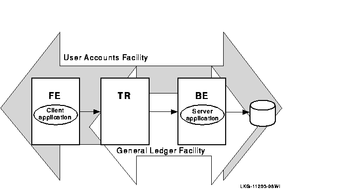
Figure 1-5 shows the logical relationship between client application, server application, frontends (FEs), routers (TRs), and backends (BEs) in the RTR environment. The database is represented by the cylinder. Two facilities are shown (indicated by the large double-headed arrows), the user accounts facility and the general ledger facility. The user accounts facility uses three nodes, FE, TR, and BE, while the general ledger facility uses only two, TR and BE.
Figure 1-5 Components in the RTR Environment
Clients send messages to servers to ask that a piece of work be done. Such requests may be bundled together into transactions. An RTR transaction consists of one or more messages that have been grouped together by a client application, so that the work done as a result of each message can be undone completely, if some part of that work cannot be done. If the system fails or is disconnected before all parts of the transaction are done, then the transaction remains incomplete.
Transaction
A transaction is a piece of work or group of operations that must be executed together to perform a consistent transformation of data. This group of operations can be distributed across many nodes serving multiple databases. Applications use services that RTR provides.
Transactional messaging
RTR provides transactional messaging in which transactions are enclosed in messages controlled by RTR.
Transactional messaging ensures that each transaction is complete, and not partially recorded. For example, a transaction or business exchange in a bank account might be to move money from a checking account to a savings account. The complete transaction is to remove the money from the checking account and add it to the savings account.
A transaction that transfers funds from one account to another consists of two individual updates: one to debit the first account, and one to credit the second account. The transaction is not complete until both actions are done. If a system performing this work goes down after the money has been debited from the checking account but before it has been credited to the savings account, the transaction is incomplete. With transactional messaging, RTR ensures that a transaction is "all or nothing"---either fully completed or discarded; either both the checking account debit and the savings account credit are done, or the checking account debit is backed out and not recorded in the database. RTR transactions have the ACID properties.
Nontransactional messaging
An application will also contain nontransactional tasks such as writing diagnostic trace messages or sending a broadcast message about a change in a stock price after a transaction has been completed.
Transaction ID
Every transaction is identified on initiation with a transaction identifier or transaction ID, with which it can be logged and tracked.
To reinforce the use of these terms in the RTR context, this section briefly reviews other uses of configuration terminology.
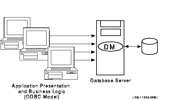
A traditional two-tier client/server environment is based on hardware that separates application presentation and business logic (the clients) from database server activities. The client hardware runs presentation and business logic software, and server hardware runs database or data manager (DM) software, also called resource managers (RM). This type of configuration is illustrated in Figure 1-6. (In all diagrams, all lines are bidirectional.)
Transaction Controller
With the C++ API, the Transaction Controller manages transactions (one at a time), channels, messages, and events.
Figure 1-6 Two-Tier Client/Server Environment
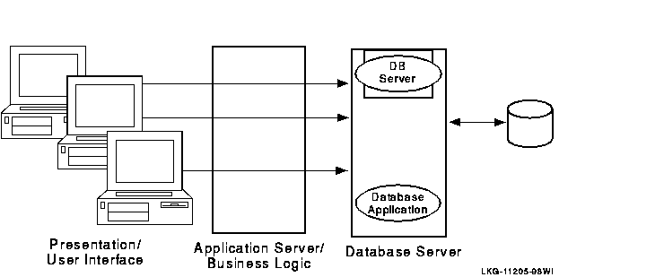
Further separation into three tiers is achieved by separating presentation software from business logic on two systems, and retaining a third physical system for interaction with the database. This is illustrated in Figure 1-7.
Figure 1-7 Three-Tier Client/Server Environment
RTR extends the three-tier model based on hardware to a multitier, multilayer, or multicomponent software model.
RTR provides a multicomponent software model where clients running on frontends, routers, and servers running on backends cooperate to provide reliable service and transactional integrity. Application users interact with the client (presentation layer) on the frontend node that forwards messages to the current router. The router in turn routes the messages to the current, appropriate backend, where server applications reside, for processing. The connection to the current router is maintained until the current router fails or connections to it are lost.
All components can reside on a single node but are typically deployed on different nodes to achieve modularity, scalability, and redundancy for availability. With different systems, if one physical node goes down or off line, another router and backend node takes over. In a slightly different configuration, you could have an application that uses an external applet running on a browser that connects to a client running on the RTR frontend. Such a configuration is shown in Figure 1-8.
Figure 1-8 Browser Applet Configuration
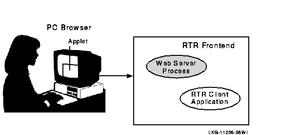
The RTR client application could be an ASP (Active Server Page) script or a process interfacing to the webserver through a standard interface such as CGI (Common Gateway Interface).
RTR provides automatic software failure tolerance and failure recovery in multinode environments by sustaining transaction integrity in spite of hardware, communications, application, or site failures. Automatic failover and recovery of service can exploit redundant or underutilized hardware and network links.
As you modularize your application and distribute its components on frontends and backends, you can add new nodes, identify usage bottlenecks, and provide redundancy to increase availability. Adding backend nodes can help divide the transactional load and distribute it more evenly. For example, you could have a single node configuration as shown in Figure 1-9, RTR with Browser, Single Node, and Database. A single node configuration can be useful during development, but would not normally be used when your application is deployed.
Figure 1-9 RTR with Browser, Single Node, and Database

When creating the configuration used by an application and defining the nodes where a facility has its frontends, routers, and backends, the setup must also define which nodes will have journal files. Each backend in an RTR configuration must have a journal file to capture transactions when other nodes are unavailable. When applications are deployed, often the backend is separated from the frontend and router, as shown in Figure 1-10.
Figure 1-10 RTR Deployed on Two Nodes

In this example, the frontend with the client and the router reside on one node, and the server resides on the backend. Frequently, routers are placed on backends rather than on frontends. A further separation of workload onto three nodes is shown in Figure 1-11.
Figure 1-11 RTR Deployed on Three Nodes

This three-node configuration separates transaction load onto three nodes, but does not provide for continuing work if one of the nodes fails or becomes disconnected from the others. In many applications, there is a need to ensure that there is a server always available to access the database.
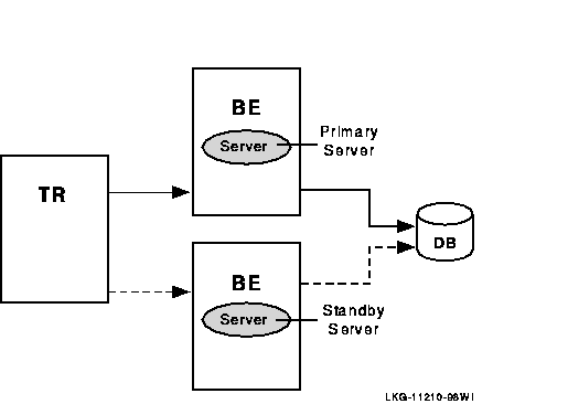
In this case, a standby server will do the job. A standby server (see Figure 1-12 is a process that can take over when the primary server is not available. Both the primary and the standby server access the same database, but the primary processes all transactions unless it is unavailable. The standby processes transactions only when the primary is unavailable. At other times, the standby can do other work. The standby server is often placed on a node other than the node where the primary server runs.
Figure 1-12 Standby Server Configuration
Transactional shadowing
To increase transaction availability, transactions can be shadowed with a shadow server. This is called transactional shadowing and is accomplished by having a second location, often at a different site, where transactions are also recorded. This is illustrated in Figure 1-13. Data are recorded in two separate data stores or databases. The router knows about both backends and sends all transactions to both backends. RTR provides the server application with the necessary information to keep the two databases synchronized.
Figure 1-13 Transactional Shadowing Configuration

RTR Journal
In the RTR environment, one data store (database or data file) is elected the primary, and a second data store is made the shadow. The shadow data store is a copy of the data store kept on the primary. If either data store becomes unavailable, all transactions continue to be processed and stored on the surviving data store. At the same time, RTR makes a record of (remembers) all transactions stored only on the shadow data store in the RTR journal by the shadow server. When the primary server and data store become available again, RTR replays the transactions in the journal to the primary data store through the primary server. This brings the data store back into synchronization.
With transactional shadowing, there is no requirement that hardware, the data store, or the operating system at different sites be the same. You could, for example, have one site running OpenVMS and another running Windows NT; the RTR transactional commit process would be the same at each site.
Transactional shadowing shadows only transactions controlled by RTR. |
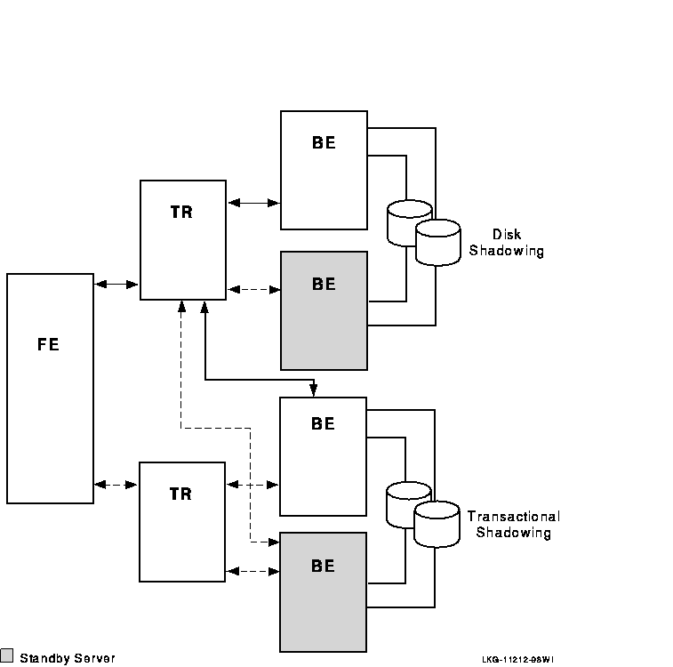
For full redundancy to assure maximum availability, a configuration could employ both disk shadowing in clusters at separate sites coupled with transactional shadowing across sites with standby servers at each site. This configuration is shown in Figure 1-14. For clarity, not all possible connections are shown. In the figure, backends running standby servers are shaded, connected to routers by dashed lines. Only one site (the upper site) does full disk shadowing; the lower site is the shadow for transactions, shadowing all transactions being done at the upper site.
Figure 1-14 Two Sites: Transactional and Disk Shadowing with Standby Servers
| Next | Contents | Index |