![[Compaq]](../../images/compaq.gif)
![[Go to the documentation home page]](../../images/buttons/bn_site_home.gif)
![[How to order documentation]](../../images/buttons/bn_order_docs.gif)
![[Help on this site]](../../images/buttons/bn_site_help.gif)
![[How to contact us]](../../images/buttons/bn_comments.gif)
![[OpenVMS documentation]](../../images/ovmsdoc_sec_head.gif)
| Document revision date: 19 July 1999 | |
![[Compaq]](../../images/compaq.gif) |
![[Go to the documentation home page]](../../images/buttons/bn_site_home.gif)
![[How to order documentation]](../../images/buttons/bn_order_docs.gif)
![[Help on this site]](../../images/buttons/bn_site_help.gif)
![[How to contact us]](../../images/buttons/bn_comments.gif)
|
![[OpenVMS documentation]](../../images/ovmsdoc_sec_head.gif)
|
|
| Previous | Contents | Index |
When the conditions for replacement cannot be met, the ETIR$C_STC_BOH_PS and ETIR$C_STC_BOH_GBL commands calculate hints and insert them into the low-order 14 bits of the instruction in the default instruction stream.
The hint field in the JSR instruction is used to index the instruction cache. The hint is correct if the low-order 16 bits of the result of
JSR + 4 + (4 * HINT < 13:0 >)
|
is equal to the low-order 16 bits of the address of the destination routine's entry point. Program execution is not affected by a wrong hint, but performance may be. Even given a correct hint, the instruction cache may not contain the desired instructions, which may then have to be fetched from memory or disk.
Hints to shareable images may no longer be correct at run time if the shareable image is relinked after the main image is created. Hints to shareable images installed with the /RESIDENT qualifier will still be correct because the position of the procedure entry relative to the beginning of a page boundary will not have changed. Hints generated for calls to the system executive, for example, calls to SYS$BASE_IMAGE.EXE or SYS$PUBLIC_VECTORS.EXE, will not be correct. The image offsets contained in their global symbol tables cannot be converted at link time into the real page offsets of the procedures in the loaded execlets.
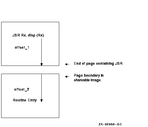
Figure B-12 Calculating a Hint to a Shareable Image

If the destination routine is inside the image being linked, the linker calculates the hint as the longword displacement between JSR + 4 and the procedure entry point. If the displacement is negative, the algorithm still works; the low-order 16 bits of JSR + 4 + <left symbol><right symbol> is still equal to the low-order 16 bits of the address of the destination routine. It is irrelevant that the high-order 16 bits of the result may not equal the high-order 16 bits of the destination routine.
If the destination routine is outside the image, the linker adds the
byte displacement from the JSR instruction to the end of the current
page (offset_1) to the byte displacement of the destination routine
from the beginning of the page (offset_2), as shown in Figure B-12.
The low-order 16 bits of the result are shifted right two bits to
generate the hint. The linker uses the EGST$L_LP_1 field in the
definition of the destination routine (from the global symbol table)
and the image page size (from the image header) to determine the offset
into the page of the procedure entry.
B.5 End-of-Module Record (EOBJ$C_EEOM)
The end-of-module (EOBJ$C_EEOM) record declares the end of the module. It must be the last record in the object module.
If the module does not contain a program section that contains the transfer address, the end-of-module (EOM) record is 10 bytes long, consisting of only the RECORD TYPE, RECORD SIZE, LINKAGE COUNT, and COMPLETION CODE fields.
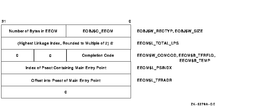
If the module does contain a program section that contains the transfer address, the EOM record is 24 bytes long. A full EOM record is shown in Figure B-13.
Figure B-13 End-of-Module Record

The fields in an EEOM record are described in the following list.
| RECORD TYPE | Name: EEOM$W_RECTYP |
| Length: 2 bytes |
The field EEOM$W_RECTYP redefines EOBJ$W_RECTYP. It must contain the value EOBJ$C_EEOM.
| RECORD SIZE | Name: EEOM$W_SIZE |
| Length: 2 bytes |
The field EEOM$W_SIZE redefines EOBJ$W_SIZE. It is the size of the entire record, including the preceding record type field.
| TOTAL LINKAGE | Name: EEOM$L_TOTAL_LPS |
| Length: 4 bytes |
This field contains the highest linkage index, rounded up to an even number, and divided by two. It is used by the linker to allocate table space after Pass 1 and to check the range of linkage indexes passed in TIR commands processed in Pass 2. The linker does not detect improper use of the highest index when rounding occurs. For example, if the highest linkage declared was 9 (yielding a value of 5 for the EEOM$L_TOTAL_LPS field), and a TIR command specifies a linkage index of 10 (which appears to be in range), unpredictable results will occur.
| COMPLETION CODE | Name: EEOM$W_COMCOD |
| Length: 2 bytes |
This field contains completion codes, which are generated by the language processor. This field may contain a value from 0 to 3, where each number corresponds to a completion code. Values from 4 to 255 are reserved by Digital. The following table lists the name, corresponding value, and meaning of each of the four completion codes.
| Value | Name | Meaning |
|---|---|---|
| 0 | EEOM$C_SUCCESS | Successful compilation or assembly; no errors detected. |
| 1 | EEOM$C_WARNING | Language processor generated warning messages. The linker issues a warning message and proceeds with the linking operation. |
| 2 | EEOM$C_ERROR | Language processor generated severe errors. The linker issues an error message, proceeds with the linking operation, but does not produce an output image file. |
| 3 | EEOM$C_ABORT | Language processor generated fatal errors. The linker aborts the linking operation. |
| 4--255 | Reserved to Digital. |
When the linker is creating a shareable image, it performs a logical OR on the completion codes from all of the modules and shareable images that contributed to it. The result is then propagated to the COMPLETION CODE field of the end-of-module record of the resulting image's global symbol table. If any module or shareable image specified a completion code other than EEOM$C_SUCCESS, any programmer who links against the resulting image will receive a warning.
| TRANSFER FLAGS | Name: EEOM$B_TFRFLG |
| Length: 1 byte |
This field is a 1-byte bit mask that contains information about the transfer address. When the EEOM$V_WKTFR bit is set, a weak transfer address is indicated; when clear, a strong transfer address is indicated. If bit EEOM$V_WKTFR is set and a transfer address has already been defined, no error results. Bits 1 to 7 are reserved and must contain zeros. Note that this field may be present only if the module contains a program section that contains the transfer address.
| ALIGNMENT BYTE | Name: EEOM$B_TEMP |
| Length: 1 byte |
Alignment byte, must be 0.
| PSECT INDEX | Name: EEOM$L_PSINDX |
| Length: 4 bytes |
This field contains the program section index of the program section within the module that contains the transfer address. Note that this field is present only if the module contains a program section that contains a transfer address.
| TRANSFER ADDRESS | Name: EEOM$L_TFRADR |
| Length: 4 bytes |
This field contains the location of the transfer address. The location
is expressed as an offset from the base of this module's contribution
to the program section that contains the transfer address. Note that
this field is present only if the module contains a program section
that contains the transfer address.
B.6 Debugger Information Records (EOBJ$C_EDBG)
The purpose of debugger information records is to allow the language processors to pass compilation information, such as descriptions of local variables, to the debugger. The transmission of this information may make use of all the functions (commands) available in the TIR command set, except for the instruction-related conditional store commands described in Section B.4.5.2.
The command stream in DBG records generates a debugger symbol table (DST). The DST immediately follows the binary of the user image, and the image header contains a descriptor of where in the file such data is written. The production of the DST in memory makes use of a separate location counter within the linker. Note that the linker does not produce an image section descriptor for the DST and that the DST is not mapped into the user's address space by the image activator. The debugger must read and map the DST.
The linker uses ETIR$C_EDBG and ETIR$C_ETBT records to produce a DST if
the image is linked with the /DEBUG qualifier. If the image is only
linked with the /TRACEBACK qualifier (the default), then the linker
skips the ETIR$C_EDBG records and builds a DST using only the
ETIR$C_ETBT records. The linker will not process the ETIR$C_EDBG
records and will skip the ETIR$C_ETBT records; if you specify
/DEBUG/NOTRACEBACK, the linker ignores the /NOTRACEBACK qualifier.
B.7 Traceback Information Records (EOBJ$C_ETBT)
Traceback information records are the means by which language processors pass information to the facility that produces a traceback of the call stack. From the point of view of the linker and its processing of these records, they are identical to DBG records. That is, they may be mixed with DBG records, and all data generated goes into the DST as if they were DBG records.
The purpose of separating the information contained in DBG records is to allow inclusion of a DST containing only traceback data when no debugging is requested at link time. If the production of traceback information is disabled at link time, these records are ignored.
| Index | Contents |
![[Go to the documentation home page]](../../images/buttons/bn_site_home.gif)
![[How to order documentation]](../../images/buttons/bn_order_docs.gif)
![[Help on this site]](../../images/buttons/bn_site_help.gif)
![[How to contact us]](../../images/buttons/bn_comments.gif)
|
| privacy and legal statement | ||
| 4548PRO_025.HTML | ||