![[Compaq]](../../images/compaq.gif)
![[Go to the documentation home page]](../../images/buttons/bn_site_home.gif)
![[How to order documentation]](../../images/buttons/bn_order_docs.gif)
![[Help on this site]](../../images/buttons/bn_site_help.gif)
![[How to contact us]](../../images/buttons/bn_comments.gif)
![[OpenVMS documentation]](../../images/ovmsdoc_sec_head.gif)
| Document revision date: 19 July 1999 | |
![[Compaq]](../../images/compaq.gif) |
![[Go to the documentation home page]](../../images/buttons/bn_site_home.gif)
![[How to order documentation]](../../images/buttons/bn_order_docs.gif)
![[Help on this site]](../../images/buttons/bn_site_help.gif)
![[How to contact us]](../../images/buttons/bn_comments.gif)
|
![[OpenVMS documentation]](../../images/ovmsdoc_sec_head.gif)
|
|
| Previous | Contents | Index |
Table A-2 shows the supported hardware components for SCSI OpenVMS Cluster systems; it also lists the minimum required revision for these hardware components. That is, for any component, you must use either the version listed in Table A-2 or a subsequent version. For host support information, refer to the DIGITAL Systems and Options Catalog on the World Wide Web at the following address:
http://www.digital.com:80/info/soc/ |
You can also access the DIGITAL Systems and Options Catalog from the OpenVMS web site by selecting Publications and then selecting this catalog.
For disk support information, refer to StorageWorks documentation. You can access the StorageWorks web site at the following address:
http://www.storage.digital.com/ |
You can also access the StorageWorks web site from the OpenVMS web site by selecting Hardware and then selecting Storage.
The SCSI interconnect configuration and all devices on the SCSI interconnect must meet the requirements defined in the ANSI Standard SCSI--2 document, or the SCSI--3 Architecture and Command standards, and the requirements described in this appendix. See also Section A.7.7 for information about other hardware devices that might be used in a SCSI OpenVMS Cluster configuration.
| Component | Supported Item | Minimum Firmware (FW) Version1 |
|---|---|---|
| Controller | HSZ40--B | 2.5 (FW) |
| HSZ50 | ||
| HSZ70 | ||
| HSZ80 | 8.3 (FW) | |
| Adapters 2 | Embedded (NCR-810 based) | |
| KZPAA (PCI to SCSI) | ||
| KZPSA (PCI to SCSI) | A11 (FW) | |
| KZPBA-CB (PCI to SCSI) | 5.53 (FW) | |
| KZTSA (TURBOchannel to SCSI) | A10-1 (FW) |
The SCSI standard defines a set of rules governing the interactions between initiators (typically, host systems) and SCSI targets (typically, peripheral devices). This standard allows the host to communicate with SCSI devices (such as disk drives, tape drives, printers, and optical media devices) without having to manage the device-specific characteristics.
The following sections describe the SCSI standard and the default modes
of operation. The discussions also describe some optional mechanisms
you can implement to enhance the default SCSI capabilities in areas
such as capacity, performance, availability, and distance.
A.4.1 Number of Devices
The SCSI bus is an I/O interconnect that can support up to 16 devices. A narrow SCSI bus supports up to 8 devices; a wide SCSI bus support up to 16 devices. The devices can include host adapters, peripheral controllers, and discrete peripheral devices such as disk or tape drives. The devices are addressed by a unique ID number from 0 through 15. You assign the device IDs by entering console commands, or by setting jumpers or switches, or by selecting a slot on a StorageWorks enclosure.
In order to connect 16 devices to a wide SCSI bus, the devices themselves must also support wide addressing. Narrow devices do not talk to hosts above ID 7. Presently, the HSZ40 does not support addresses above 7. Host adapters that support wide addressing are KZTSA, KZPSA, and the QLogic wide adapters (KZPBA, KZPDA, ITIOP, P1SE, and P2SE). Only the KZPBA--CB is supported in a multihost SCSI OpenVMS Cluster configuration. |
When configuring more devices than the previous limit of eight, make sure that you observe the bus length requirements (see Table A-4).
To configure wide IDs on a BA356 box, refer to the BA356 manual StorageWorks Solutions BA356-SB 16-Bit Shelf User's Guide (order number EK-BA356-UG). Do not configure a narrow device in a BA356 box that has a starting address of 8.
To increase the number of devices on the SCSI interconnect, some devices implement a second level of device addressing using logical unit numbers (LUNs). For each device ID, up to eight LUNs (0--7) can be used to address a single SCSI device as multiple units. The maximum number of LUNs per device ID is eight.
When connecting devices to a SCSI interconnect, each device on the interconnect must have a unique device ID. You may need to change a device's default device ID to make it unique. For information about setting a single device's ID, refer to the owner's guide for the device. |
The default mode of operation for all SCSI devices is 8-bit asynchronous mode. This mode, sometimes referred to as narrow mode, transfers 8 bits of data from one device to another. Each data transfer is acknowledged by the device receiving the data. Because the performance of the default mode is limited, the SCSI standard defines optional mechanisms to enhance performance. The following list describes two optional methods for achieving higher performance:
Because all communications on a SCSI interconnect occur between two devices at a time, each pair of devices must negotiate to determine which of the optional features they will use. Most, if not all, SCSI devices implement one or more of these options.
Table A-3 shows data rates when using 8- and 16-bit transfers with standard, fast, and ultra synchronous modes.
| Mode | Narrow (8-bit) | Wide (16-bit) |
|---|---|---|
| Standard | 5 | 10 |
| Fast | 10 | 20 |
| Ultra | 20 | 40 |
The maximum length of the SCSI interconnect is determined by the signaling method used in the configuration and by the data transfer rate. There are two types of electrical signaling for SCSI interconnects:
Table A-4 summarizes how the type of signaling method affects SCSI interconnect distances.
| Signaling Technique | Rate of Data Transfer | Maximum Cable Length |
|---|---|---|
| Single ended | Standard | 6 m 1 |
| Single ended | Fast | 3 m |
| Single ended | Ultra | 20.5 m 2 |
| Differential | Standard or fast | 25 m |
| Differential | Ultra | 25.5 m 2 |
The DWZZA, DWZZB, and DWZZC converters are single-ended to differential converters that you can use to connect single-ended and differential SCSI interconnect segments. The DWZZA is for narrow (8-bit) SCSI buses, the DWZZB is for wide (16-bit) SCSI buses, and the DWZZC is for wide Ultra SCSI buses.
The differential segments are useful for the following:
Because the DWZZA, the DWZZB, and the DWZZC are strictly signal
converters, you can not assign a SCSI device ID to them. You can
configure a maximum of two DWZZA or two DWZZB converters in the path
between any two SCSI devices. Refer to the StorageWorks UltraSCSI
Configuration Guidelines for information on configuring the DWZZC.
A.4.4 Cabling and Termination
Each single-ended and differential SCSI interconnect must have two terminators, one at each end. The specified maximum interconnect lengths are measured from terminator to terminator.
The interconnect terminators are powered from the SCSI interconnect line called TERMPWR. Each StorageWorks host adapter and enclosure supplies the TERMPWR interconnect line, so that as long as one host or enclosure is powered on, the interconnect remains terminated.
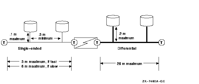
Devices attach to the interconnect by short cables (or etch) called stubs. Stubs must be short in order to maintain the signal integrity of the interconnect. The maximum stub lengths allowed are determined by the type of signaling used by the interconnect, as follows:
Additionally, the minimum distance between stubs on a single-ended interconnect is .3 m. Refer to Figure A-3 for an example of this configuration.
Terminate single-ended and differential buses individually, even when using DWZZx converters. |
When you are extending the SCSI bus beyond an existing terminator, it is necessary to disable or remove that terminator.
Figure A-3 Maximum Stub Lengths
The hardware configuration that you choose depends on a combination of factors:
Refer to the OpenVMS Cluster Software Software Product Description (SPD 29.78.xx) for configuration limits.
The following sections provide guidelines for building SCSI
configurations and describe potential configurations that might be
suitable for various sites.
A.5.1 Systems Using Add-On SCSI Adapters
Shared SCSI bus configurations typically use optional add-on KZPAA, KZPSA, KZPBA, and KZTSA adapters. These adapters are generally easier to configure than internal adapters because they do not consume any SCSI cable length. Additionally, when you configure systems using add-on adapters for the shared SCSI bus, the internal adapter is available for connecting devices that cannot be shared (for example, SCSI tape, floppy, and CD-ROM drives).
When using add-on adapters, storage is configured using BA350, BA353, or HSZxx StorageWorks enclosures. These enclosures are suitable for all data disks, and for shared OpenVMS Cluster system and quorum disks. By using StorageWorks enclosures, it is possible to shut down individual systems without losing access to the disks.
The following sections describe some SCSI OpenVMS Cluster
configurations that take advantage of add-on adapters.
A.5.1.1 Building a Basic System Using Add-On SCSI Adapters
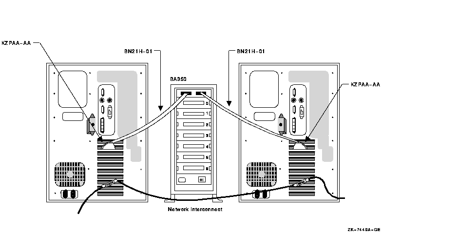
Figure A-4 shows a logical representation of a basic configuration using SCSI adapters and a StorageWorks enclosure. This configuration has the advantage of being relatively simple, while still allowing the use of tapes, floppies, CD-ROMs, and disks with nonshared files (for example, page files and swap files) on internal buses. Figure A-5 shows this type of configuration using AlphaServer 1000 systems and a BA350 enclosure.
The BA350 enclosure uses 0.9 m of SCSI cabling, and this configuration typically uses two 1-m SCSI cables. (A BA353 enclosure also uses 0.9 m, with the same total cable length.) The resulting total cable length of 2.9 m allows fast SCSI mode operation.
Although the shared BA350 storage enclosure is theoretically a single point of failure, this basic system is a very reliable SCSI OpenVMS Cluster configuration. When the quorum disk is located in the BA350, you can shut down either of the AlphaStation systems independently while retaining access to the OpenVMS Cluster system. However, you cannot physically remove the AlphaStation system, because that would leave an unterminated SCSI bus.
If you need the ability to remove a system while your OpenVMS Cluster system remains operational, build your system using DWZZx converters, as described in Section A.5.1.2. If you need continuous access to data if a SCSI interconnect fails, you should do both of the following:
In Figure A-4 and the other logical configuration diagrams in this appendix, the required network interconnect is not shown.
Figure A-4 Conceptual View: Basic SCSI System
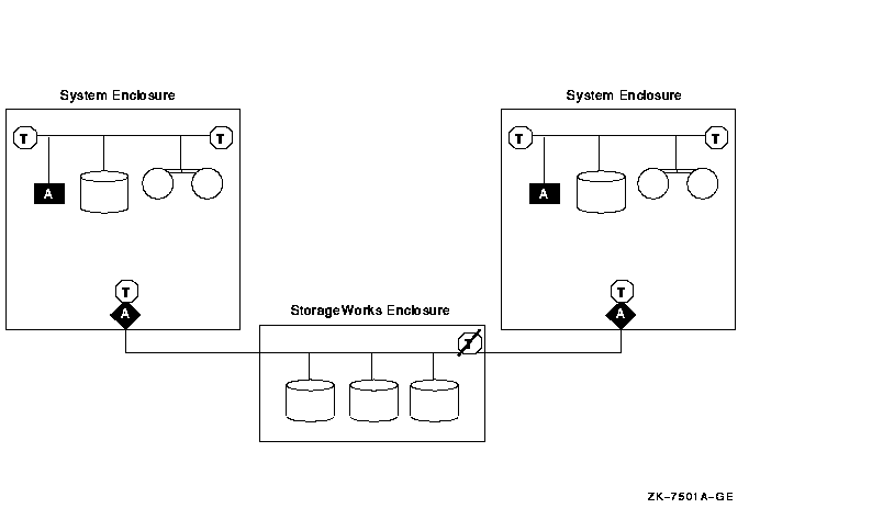
Figure A-5 Sample Configuration: Basic SCSI System Using AlphaServer 1000, KZPAA Adapter, and BA350 Enclosure
If you need additional enclosures, or if the needs of your site require a greater physical separation between systems, or if you plan to use HSZ controllers, you can use a configuration in which DWZZx converters are placed between systems with single-ended signaling and a differential-cabled SCSI bus.
DWZZx converters provide additional SCSI bus length capabilities, because the DWZZx allows you to connect a single-ended device to a bus that uses differential signaling. As described in Section A.4.3, SCSI bus configurations that use differential signaling may span distances up to 25 m, whereas single-ended configurations can span only 3 m when fast-mode data transfer is used.
DWZZx converters are available as standalone, desktop components or as StorageWorks compatible building blocks. DWZZx converters can be used with the internal SCSI adapter or the optional KZPAA adapters.
The HSZ40 is a high-performance differential SCSI controller that can be connected to a differential SCSI bus, and supports up to 72 SCSI devices. An HSZ40 can be configured on a shared SCSI bus that includes DWZZx single-ended to differential converters. Disk devices configured on HSZ40 controllers can be combined into RAID sets to further enhance performance and provide high availability.
Figure A-6 shows a logical view of a configuration that uses additional DWZZAs to increase the potential physical separation (or to allow for additional enclosures and HSZ40s), and Figure A-7 shows a sample representation of this configuration.
Figure A-6 Conceptual View: Using DWZZAs to Allow for Increased Separation or More Enclosures
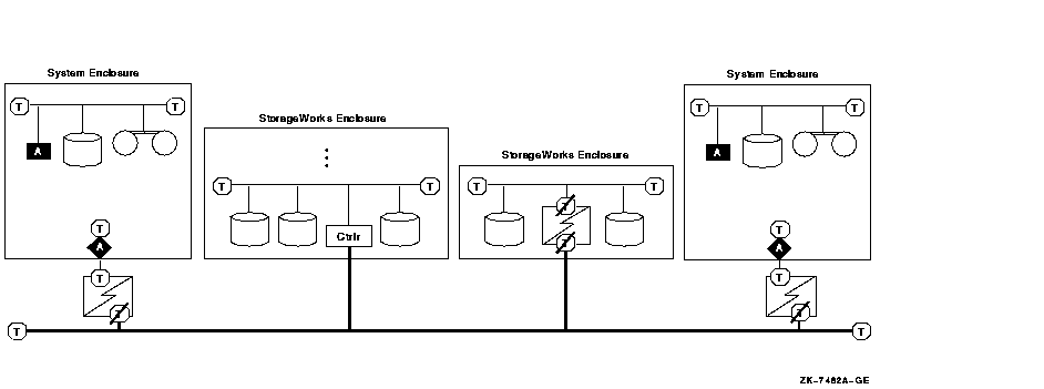
Figure A-7 Sample Configuration: Using DWZZAs to Allow for Increased Separation or More Enclosures
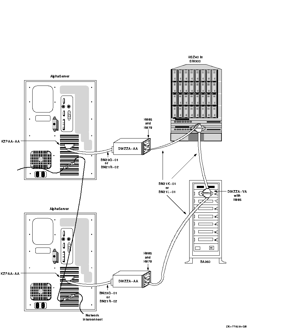
Figure A-8 shows how a three-host SCSI OpenVMS Cluster system might be configured.
Figure A-8 Sample Configuration: Three Hosts on a SCSI Bus
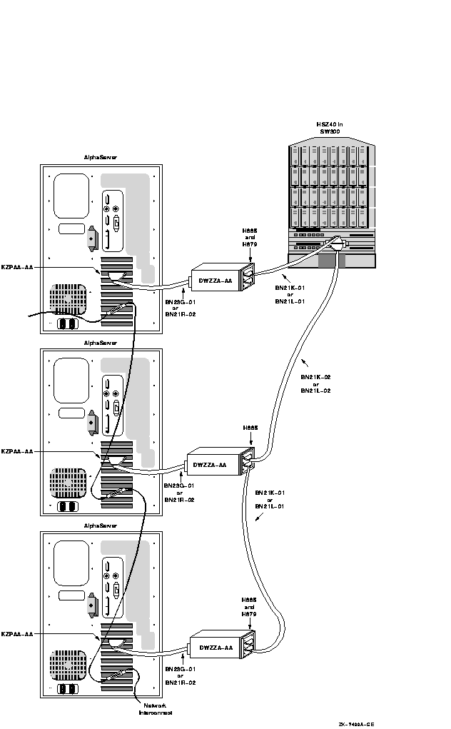
Figure A-9 is a sample configuration with two KZPSA adapters on the same SCSI bus. In this configuration, the SCSI termination has been removed from the KZPSA, and external terminators have been installed on "Y" cables. This allows you to remove the KZPSA adapter from the SCSI bus without rendering the SCSI bus inoperative. The capability of removing an individual system from your SCSI OpenVMS Cluster configuration (for maintenance or repair) while the other systems in the cluster remain active gives you an especially high level of availability.
Please note the following about Figure A-9:
Figure A-9 Sample Configuration: SCSI System Using Differential Host Adapters (KZPSA)
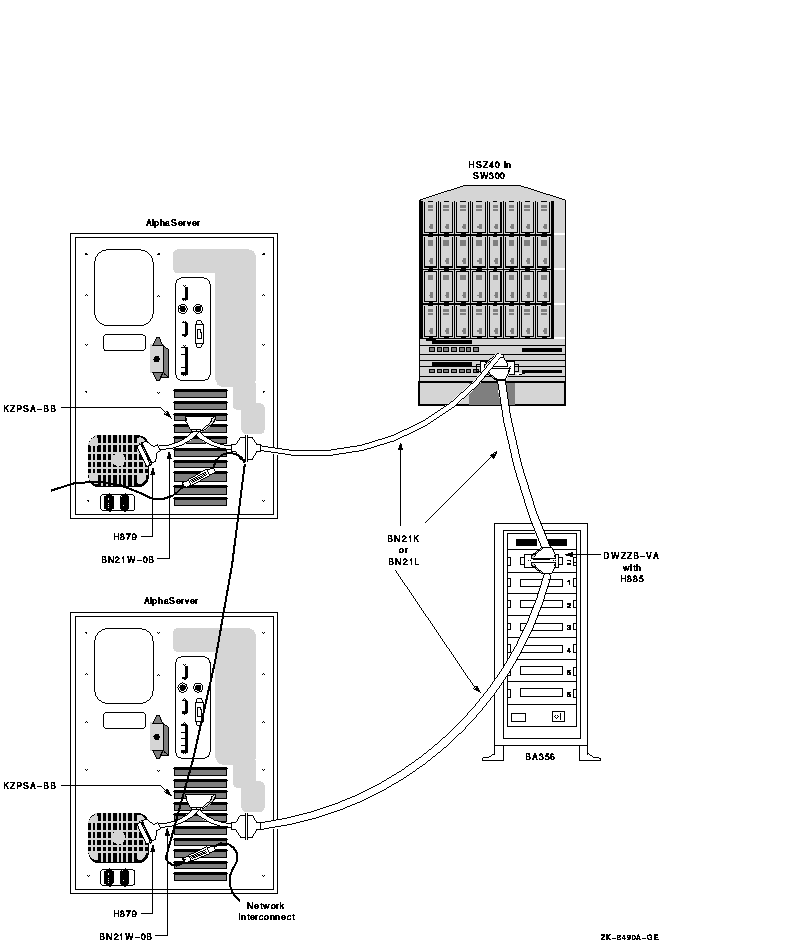
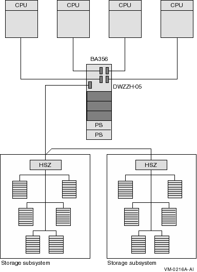
The differential SCSI bus in the configuration shown in Figure A-9 is chained from enclosure to enclosure and is limited to 25 m in length. (The BA356 does not add to the differential SCSI bus length. The differential bus consists only of the BN21W-0B "Y" cables and the BN21K/BN21L cables.) In configurations where this cabling scheme is inconvenient or where it does not provide adequate distance, an alternative radial scheme can be used.
The radial SCSI cabling alternative is based on a SCSI hub. Figure A-10 shows a logical view of the SCSI hub configuration, and Figure A-11 shows a sample representation of this configuration.
Figure A-10 Conceptual View: SCSI System Using a SCSI Hub
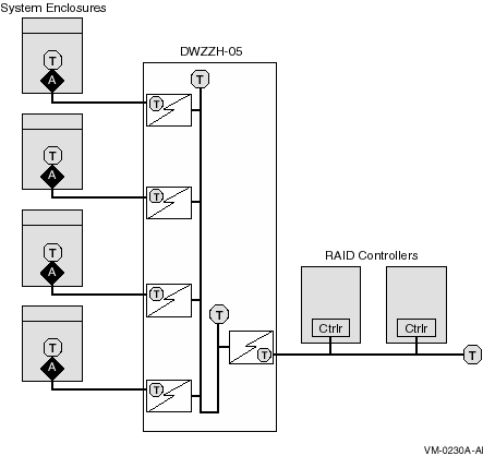
Figure A-11 shows a sample representation of a SCSI hub configuration.
Figure A-11 Sample Configuration: SCSI System with SCSI Hub Configuration
This section describes the steps required to set up and install the hardware in a SCSI OpenVMS Cluster system. The assumption in this section is that a new OpenVMS Cluster system, based on a shared SCSI bus, is being created. If, on the other hand, you are adding a shared SCSI bus to an existing OpenVMS Cluster configuration, then you should integrate the procedures in this section with those described in OpenVMS Cluster Systems to formulate your overall installation plan.
Table A-5 lists the steps required to set up and install the hardware in a SCSI OpenVMS Cluster system.
| Step | Description | Reference |
|---|---|---|
| 1 | Ensure proper grounding between enclosures. | Section A.6.1 and Section A.7.8 |
| 2 | Configure SCSI host IDs. | Section A.6.2 |
| 3 | Power up the system and verify devices. | Section A.6.3 |
| 4 | Set SCSI console parameters. | Section A.6.4 |
| 5 | Install the OpenVMS operating system. | Section A.6.5 |
| 6 | Configure additional systems. | Section A.6.6 |
| Previous | Next | Contents | Index |
![[Go to the documentation home page]](../../images/buttons/bn_site_home.gif)
![[How to order documentation]](../../images/buttons/bn_order_docs.gif)
![[Help on this site]](../../images/buttons/bn_site_help.gif)
![[How to contact us]](../../images/buttons/bn_comments.gif)
|
| privacy and legal statement | ||
| 6318PRO_018.HTML | ||