![[Compaq]](../../images/compaq.gif)
![[Go to the documentation home page]](../../images/buttons/bn_site_home.gif)
![[How to order documentation]](../../images/buttons/bn_order_docs.gif)
![[Help on this site]](../../images/buttons/bn_site_help.gif)
![[How to contact us]](../../images/buttons/bn_comments.gif)
![[OpenVMS documentation]](../../images/ovmsdoc_sec_head.gif)
| Document revision date: 19 July 1999 | |
![[Compaq]](../../images/compaq.gif) |
![[Go to the documentation home page]](../../images/buttons/bn_site_home.gif)
![[How to order documentation]](../../images/buttons/bn_order_docs.gif)
![[Help on this site]](../../images/buttons/bn_site_help.gif)
![[How to contact us]](../../images/buttons/bn_comments.gif)
|
![[OpenVMS documentation]](../../images/ovmsdoc_sec_head.gif)
|
|
| Previous | Contents | Index |
In a MEMORY CHANNEL configuration, a section of system physical address space is shared among all nodes. When a system writes data to this address space, the MEMORY CHANNEL hardware also performs a global write so that this data is stored in the memories of other systems. In other words, when a node's CPU writes data to the PCI address space occupied by the MEMORY CHANNEL adapter, the data is sent across the MEMORY CHANNEL interconnect to the other nodes. The other nodes' PCI adapters map this data into their own memory. This infrastructure enables a write to an I/O address on one system to get mapped to a physical address on the other system. The next two figures explain this in more detail.
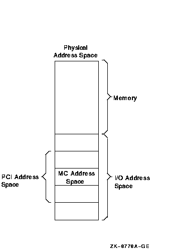
Figure B-8 shows how MEMORY CHANNEL global address space is addressed in physical memory.
Figure B-8 Physical Memory and I/O Address Space

Figure B-8 shows the typical address space of a system, divided into physical memory and I/O address space. Within the PCI I/O address space, MEMORY CHANNEL consumes 128 to 512 MB of address space. Therefore, the MEMORY CHANNEL PCI adapter can be addressed within this space, and the CPU can write data to it.
Every system in a MEMORY CHANNEL cluster allocates this address space for MEMORY CHANNEL data and communication. By using this address space, a CPU can perform global writes to the memories of other nodes.
To explain global writes more fully, Figure B-9 shows the internal bus architecture of two nodes, node A and node B.
Figure B-9 MEMORY CHANNEL Bus Architecture

In the example shown in Figure B-9, node A is performing a global write to node B's memory, in the following sequence:
If all nodes in the cluster agree to address MEMORY CHANNEL global address space in the same way, they can virtually "share" the same address space and the same data. This is why MEMORY CHANNEL address space is depicted as a common, central address space in Figure B-9.
MEMORY CHANNEL global address space is divided into pages of 8 KB (8,192 bytes). These are called MC pages. These 8 KB pages can be mapped similarly among systems.
The "shared" aspect of MEMORY CHANNEL global address space is set up using the page control table, or PCT, in the PCI adapter. The PCT has attributes that can be set for each MC page. Table B-3 explains these attributes.
| Attribute | Description |
|---|---|
| Broadcast | Data is sent to all systems or, with a node ID, data is sent to only the specified system. |
| Loopback | Data that is sent to the other nodes in a cluster is also written to memory by the PCI adapter in the transmitting node. This provides message order guarantees and a greater ability to detect errors. |
| Interrupt | Specifies that if a location is written in this MC page, it generates an interrupt to the CPU. This can be used for notifying other nodes. |
| Suppress transmit/receive after error | Specifies that if an error occurs on this page, transmit and receive operations are not allowed until the error condition is cleared. |
| ACK | A write to a page causes each receiving system's adapter to respond with an ACK (acknowledge), ensuring that a write (or other operation) has occurred on remote nodes without interrupting their hosts. This is used for error checking and error recovery. |
MEMORY CHANNEL software comes bundled with the OpenVMS Cluster software. After setting up the hardware, you configure the MEMORY CHANNEL software by responding to prompts in the CLUSTER_CONFIG.COM procedure. A prompt asks whether you want to enable MEMORY CHANNEL for node-to-node communications for the local computer. By responding "Yes", MC_SERVICES_P2, the system parameter that controls whether MEMORY CHANNEL is in effect, is set to 1. This setting causes the driver, PMDRIVER, to be loaded and the default values for the other MEMORY CHANNEL system parameters to take effect.
For a description of all the MEMORY CHANNEL system parameters, refer to the OpenVMS Cluster Systems manual.
For more detailed information about setting up the MEMORY CHANNEL hub, link cables, and PCI adapters, see the MEMORY CHANNEL User's Guide, order number EK-PCIMC-UG.A01.
This appendix describes the CI-to-PCI adapter (CIPCA) which was introduced in OpenVMS Alpha Version 6.2--1H2 and is supported on all subsequent versions, except OpenVMS Version 7.0. The CIPCA adapter supports specific Alpha servers and OpenVMS Cluster configurations.
This appendix contains the following sections:
The CIPCA adapter, developed in partnership with CMD Technologies, enables Alpha servers with PCI buses or with a PCI bus and an EISA bus to connect to the CI. The CIPCA adapter provides the following features and benefits:
| Feature | Benefit |
|---|---|
| Lower entry cost and more configuration choices | If you require midrange compute power for your business needs, CIPCA enables you to integrate midrange Alpha servers into your existing CI cluster. |
| High-end Alpha speed and power | If you require maximum compute power, you can use the CIPCA with both the AlphaServer 8200 systems and AlphaServer 8400 systems that have PCI and EISA I/O subsystems. |
| Cost-effective Alpha migration path | If you want to add Alpha servers to an existing CI VAXcluster, CIPCA provides a cost-effective way to start migrating to a mixed-architecture cluster in the price/performance range that you need. |
| Advantages of the CI |
The CIPCA connects to the CI, which offers the following advantages:
|
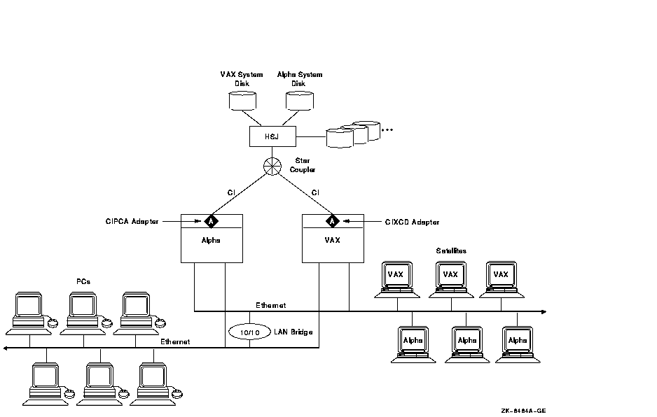
Figure C-1 shows an example of a mixed-architecture CI OpenVMS Cluster that has two servers: an Alpha and a VAX.
Figure C-1 CIPCA in a Mixed-Architecture OpenVMS Cluster

As Figure C-1 shows, you can use the CIPCA adapter to connect an Alpha server to a CI OpenVMS Cluster that contains a VAX server with a CIXCD (or CIBCA-B) adapter. This enables you to smoothly integrate an Alpha server into a cluster that previously comprised only high-end VAX systems.
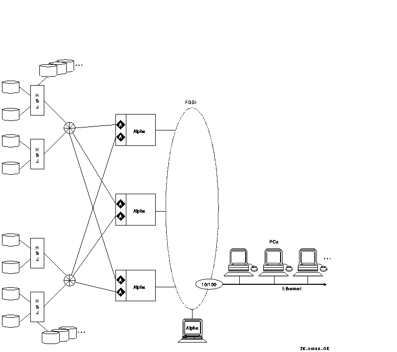
Figure C-2 shows another example of a configuration that uses the CIPCA to connect systems with the CI. In this example, each Alpha has two CIPCA adapters that allow connectivity to multiple CI star couplers and HSJ storage controllers for I/O load balancing or for OpenVMS shadow-set member isolation. Also, the Alpha systems are connected to a high-speed FDDI interconnect that provides additional connectivity for PC clients and OpenVMS satellites.
Figure C-2 CIPCA in an Alpha OpenVMS Cluster

Figure C-1 and Figure C-2 show that the CIPCA makes the performance, availability, and large storage access of the CI available to a wide variety of users. The CI has a high maximum throughput. Both the PCI-based CIPCA and the XMI based CIXCD are highly intelligent microprocessor-controlled adapters that consume minimal CPU overhead.
Because the effective throughput of the CI bus is high, the CI interconnect is not likely to be a bottleneck. In large configurations like the one shown in Figure C-2, multiple adapters and CI connections provide excellent availability and throughput.
Although not shown in Figure C-1 and Figure C-2, you can increase
availablity by placing disks on a SCSI interconnect between a pair of
HSJ controllers and connecting each HSJ to the CI.
C.2 Technical Specifications
The CIPCA is a two-slot optional adapter. Two CIPCA models are available, the CIPCA-AA and the CIPCA-BA.
The CIPCA-AA was introduced first. It requires one PCI backplane slot and one EISA backplane slot. The EISA slot supplies only power (not bus signals) to the CIPCA. The CIPCA-AA is suitable for older systems with a limited number of PCI slots.
The CIPCA-BA requires two PCI slots and is intended for newer systems with a limited number of EISA slots.
The CIPCA driver is named the SYS$PCAdriver. It is included in the OpenVMS operating system software.
Table C-1 shows the performance of the CIPCA in relation to the CIXCD adapter.
| Performance Metric | CIPCA | CIXCD |
|---|---|---|
| Read request rate (I/Os) | 4900 | 5500 |
| Read data Rate (MB/s) | 10.6 | 10.5 |
| Write request rate (I/Os) | 4900 | 4500 |
| Write data rate (MB/s) | 9.8 | 5.8 |
| Mixed request rate (I/Os) | 4800 | 5400 |
| Mixed data rate (MB/s) | 10.8 | 9.2 |
For information about installing and operating the CIPCA, refer to the
hardware manual that came with your CIPCA adapter: CIPCA PCI-CI
Adapter User's Guide.
C.3 Configuration Support and Restrictions
The CIPCA adapter is supported by AlphaServers with PCI buses, by
CI-connected VAX host systems, by storage controllers, and by the CI
star coupler expander.
C.3.1 AlphaServer Support
Table C-2 describes CIPCA support on AlphaServer systems with PCI buses, including the maximum number of CIPCAs supported on each system.
| System | Maximum CIPCAs | Comments |
|---|---|---|
| AlphaServer 8400 | 26 | Can use a combination of CIPCA and CIXCD adapters, not to exceed 26. Prior to OpenVMS Version 7.1, the maximum is 10. |
| AlphaServer 8200 | 26 | Prior to OpenVMS Version 7.1, the maximum is 10. |
| AlphaServer 4000, 4100 | 3 | When using three CIPCAs, one must be a CIPCA-AA and two must be CIPCA-BA. |
| AlphaServer 4000 plus I/O expansion module | 6 | When using six CIPCAs, only three can be CIPCA-AA. |
| AlphaServer 1200 | 2 | First supported in OpenVMS Version 7.1-1H1. |
| AlphaServer 2100A | 3 | |
| AlphaServer 2000, 2100 | 2 | Only one can be a CIPCA-BA. |
For CI-connected host systems, CIPCA is supported by any OpenVMS VAX host using CIXCD or CIBCA-B as well as by any OpenVMS Alpha server host using CIPCA or CIXCD. This means that an Alpha server using the CIPCA adapter can coexist on a CI bus with VAX systems using CIXCD and CIBCA-B CI adapters.
The maximum number of systems supported in an OpenVMS Cluster system,
96, is not affected by the use of one or more CIPCAs, although the
maximum number of CI nodes is limited to 16 (see Section C.3.4).
C.3.3 Storage Controller Support
The CIPCA adapter can coexist on a CI bus with all variants of the HSC/HSJ controllers except the HSC50. Certain controllers require specific firmware and hardware, as shown in Table C-3.
| Controller | Requirement |
|---|---|
| HSJ30, HSC40 | HSOF Version 2.5 (or higher) firmware |
| HSC40, HSC70 | Revision F (or higher) L109 module |
A CI star coupler expander (CISCE) can be added to any star coupler to
increase its connection capacity to 32 ports. The maximum number of
CPUs that can be connected to a star coupler is 16, regardless of the
number of ports.
C.3.5 Configuration Restrictions
Note the following configuration restrictions:
CIPCA-AA with EISA-Slot Link Module Rev. A01
For the CIPCA-AA adapter with the EISA-slot link module Rev. A01, use the DIP switch settings described here to prevent arbitration timeout errors. Under heavy CI loads, arbitration timeout errors can cause CI path errors and CI virtual circuit closures.
The DIP switch settings on the CIPCA-AA link module are used to specify cluster size and the node address. Follow these instructions when setting the DIP switches for link module Rev. A01 only:
These restrictions do not apply to the EISA slot link module Rev. B01 and higher or to the PCI-slot link module of the CIPCA-BA.
HSJ50 Firmware Requirement for Use of 4K CI Packets
Do not attempt to enable the use of 4K CI packets by the HSJ50
controller unless the HSJ50 firmware is Version 5.0J--3 or higher. If
the HSJ50 firmware version is less than Version 5.0J--3 and 4K CI
packets are enabled, data can become corrupted. If your HSJ50 firmware
does not meet this requirement, contact your Compaq support
representative.
C.4 Installation Requirements
When installing CIPCA adapters in your cluster, observe the following
version-specific requirements.
C.4.1 Managing Bus Addressable Pool (BAP) Size
The CIPCA, CIXCD, and KFMSB adapters use bus-addressable pool (BAP). Starting with OpenVMS Version 7.1, AUTOGEN controls the allocation of BAP. After installing or upgrading the operating system, you must run AUTOGEN with the FEEDBACK qualifier. When you run AUTOGEN in this way, the following four system parameters are set:
The BAP allocation amount depends on the adapter type, the number of adapters, and the version of the operating system. The size of physical memory determines whether the BAP remains separate or is merged with normal, nonpaged dynamic memory (NPAGEDYN), as shown in Table C-4.
| Adapter | Version 7.1 | Version 7.2 | Separate BAP or Merged |
|---|---|---|---|
| CIPCA | 4 MB | 2 MB | Separate if physical memory >1 GB; otherwise merged |
| CIXCD | 4 MB | 2 MB | Separate if physical memory >4 GB; otherwise merged |
| KFMSB | 8 MB | 4 MB | Separate if physical memory >4 GB; otherwise merged |
For systems whose BAP is merged with nonpaged pool, the initial amount and maximum amount of nonpaged pool (as displayed by the DCL command SHOW MEMORY/POOL/FULL) do not match the value of the SYSGEN parameters NPAGEDYN and NPAGEVIR. Instead, the value of SYSGEN parameter NPAG_BAP_MIN is added to NPAGEDYN to determine the initial size, and the value of NPAG_BAP_MAX is added to NPAGEVIR to determine the maximum size.
Your OpenVMS system may not require as much merged pool as the sum of
these SYSGEN parameters. After your system has been running a few days,
use AUTOGEN with the FEEDBACK qualifier to fine-tune the amount of
memory allocated for the merged, nonpaged pool.
C.4.2 AUTOCONFIGURE Restriction for OpenVMS Version 6.2-1H2 and OpenVMS Version 6.2-1H3
When you perform a normal installation boot, AUTOCONFIGURE runs
automatically. AUTOCONFIGURE is run from
SYS$STARTUP:VMS$DEVICE_STARTUP.COM (called from
SYS$SYSTEM:STARTUP.COM), unless disabled by SYSMAN. If you are running
OpenVMS Version 6.2-1H2 or OpenVMS Version 6.2-1H3 and you have
customized your booting sequence, make sure that AUTOCONFIGURE runs or
that you explicitly configure all CIPCA devices before
SYSTARTUP_VMS.COM exits.
C.5 DECevent for Analyzing CIPCA Errors
To analyze error log files for CIPCA errors, use DECevent. The DCL command ANALYZE/ERROR_LOG has not been updated to support CIPCA and other new devices; using that command will result in improperly formatted error log entries.
Install the DECevent kit supplied on the OpenVMS Alpha CD-ROM. Then use the following DCL commands to invoke DECevent to analyze dump files:
For more information about using DECevent, use the DCL HELP DIAGNOSE
command.
C.6 Performance Recommendations
To enhance performance, follow the recommendations that pertain to your
configuration.
C.6.1 Synchronous Arbitration
CIPCA uses a new, more optimal CI arbitration algorithm called synchronous arbitration instead of the older asynchronous arbitration algorithm. The two algorithms are completely compatible. Under CI saturation conditions, both the old and new algorithms are equivalent and provide equitable round-robin access to all nodes. However, with less traffic, the new algorithm provides the following benefits:
Support for synchronous arbitration is latent in the HSJ controller family. In configurations containing both CIPCAs and HSJ controllers, enabling the HSJs to use synchronous arbitration is recommended.
The HSJ CLI command to do this is:
CLI> SET THIS CI_ARB = SYNC |
This command will take effect upon the next reboot of the HSJ.
C.6.2 Maximizing CIPCA Performance With an HSJ50
To maximize the performance of the CIPCA adapter with an HSJ50 controller, it is advisable to enable the use of 4K CI packets by the HSJ50. To do this, your HSJ50 firmware revision level must be at Version 5.0J--3 or higher.
Do not attempt to do this if your HSJ50 firmware revision level is not Version 5.0J--3 or higher, because data can become corrupted. |
To enable the use of 4K CI packets, specify the following command at the HSJ50 console prompt:
CLI> SET THIS_CONTROLLER CI_4K_PACKET_CAPABILITY |
This command takes effect when the HSJ50 is rebooted.
| Previous | Next | Contents | Index |
![[Go to the documentation home page]](../../images/buttons/bn_site_home.gif)
![[How to order documentation]](../../images/buttons/bn_order_docs.gif)
![[Help on this site]](../../images/buttons/bn_site_help.gif)
![[How to contact us]](../../images/buttons/bn_comments.gif)
|
| privacy and legal statement | ||
| 6318PRO_023.HTML | ||