GC gc;
                    .
                    .
                    .
static void doButtonPress(eventP)
XEvent *eventP;
{

(1)  char dash_list[] = {20,5,10};
    x1 = y1 = 100;
    x2 = y2 = 550;

    XSetBackground(dpy, gc, doDefineColor(4));
(2)  XSetLineAttributes(dpy, gc, 0, LineDoubleDash, 0, 0);
(3)  XSetDashes(dpy, gc, 0, dash_list, 3);
    XDrawLine(dpy, win, gc, x1, y1, x2, y2);
}
|
- The dash_list variable defines the length of odd and even dashes. The first and third elements of the initialization list specify even dashes; the second element specifies odd dashes.
- The SET LINE ATTRIBUTES routine enables the
client to define line width, style, cap style, and join style in one
call.
The SET LINE ATTRIBUTES routine has the following format:
XSetLineAttributes(display, gc_id, line_width, line_style, cap_style,
join_style)
The zero cap_style argument specifies the default cap style. - If using the CREATE GC routine to set line
dashes, odd and even dashes must have equal length. The SET DASHES
routine enables the client to define dashes of varying length. The SET
DASHES routine has the following format:
XSetDashes(display, gc_id, dash_offset, dash_list, dash_list_len)
The dash_list_len argument specifies the length of the dash list.
Figure 4-11 Line Defined Using GC Routines

4.4 Copying, Changing, and Freeing Graphics Contexts
In addition to defining a graphics context, clients can copy defined characteristics from one GC data structure into another. To copy a GC data structure, use COPY GC. The COPY GC routine has the following format:
|
XCopyGC(display, src_gc_id, gc_mask, dst_gc_id) |
The gc_mask argument selects values to be copied from the source graphics context (src_gc_id). Use the method described in Section 4.2 for assigning values to a GRAPHICS CONTEXT.
The dst_gc_id argument specifies the new graphics context into which the server copies values.
After creating a graphics context structure, change values as needed using CHANGE GC. The following code fragment, which alters the values of the line drawn by Example 4-1, illustrates changing a graphics context structure:
                    .
                    .
                    .
    xgcv.line_width = 10;
    xgcv.line_style = LineSolid;

    XChangeGC(dpy,gc,GCLineWidth | GCLineStyle,&xgcv);
                    .
                    .
                    .
|
The previous example illustrates defining a new line style and width,
and changing the graphics context to reflect the new values.
4.5 Using Graphics Characteristics Efficiently
The server must revalidate a graphics context whenever a client redefines it. Causing the server to revalidate a graphics context unnecessarily can seriously degrade performance.
The server revalidates a graphics context when one of the following conditions occurs:
- A client associates the graphics context with a different window.
- The graphics context clip list changes. Changes in the clip list can happen either when a client changes the graphics context clip origin or when the server modifies the clip list in response to overlapping windows.
- Any member of the graphics context changes.
To minimize revalidating the graphics context, submit as a group the requests to the server that identify the same window and graphics context. Grouping requests enables the server to revalidate the graphics context once instead of many times.
When it is necessary to change the value of graphics context members frequently, creating a new graphics context is more efficient than redefining an existing one, provided the client creates no more than 50 graphics contexts.
Chapter 5
Using Color
Color is one of many attributes that clients can define when creating a window or a graphics object. Depending on display hardware, clients can define color as black or white, as shades of gray, or as a spectrum of hues. Section 5.2 describes color definition in detail.
Xlib offers clients the choice of either sharing colors with other clients or, when hardware supports it, allocating colors for exclusive use.
A client that does not have to change colors can share them with other clients. By sharing colors, the client saves color resources.
When a client needs to change colors, the client must allocate them for its exclusive use. For example, the client might indicate the flow through a pipeline by changing colors, rather than redrawing the entire pipeline schematic. In this case, the client would allocate for exclusive use colors that represent pipeline flow.
This chapter introduces color management using Xlib and describes how to share and allocate color resources. The chapter includes the following topics:
- Color fundamentals---A description of pixels and planes, color indices, cells, and maps
- Matching color requirements to display types---How display types affect color presentation
- Sharing color resources---How to share color resources with other clients
- Allocating colors for exclusive use---How to reserve colors for a single client
- Querying color resources---How to return values of color map entries
- Freeing color resources---How to release color resources
The concepts presented in this chapter apply to managing the color of
both windows and graphic objects.
5.1 Pixels and Color Maps
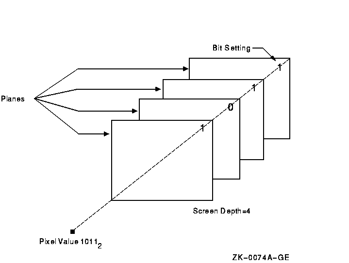
The color of a window or graphics object depends on the values of pixels that constitute it. The number of bits associated with each pixel determines the number of possible pixel values. On a monochrome screen, one bit corresponds to each pixel. The number of possible pixel values is 2. Pixels are either zero or one, black or white.
On a monochrome screen, all bits that define an image reside on one plane. A plane is an allocation of memory with a one-to-one correspondence between bits and pixels. The number of planes is the depth of the screen.
The depth of intensity of color screens is greater than one. More than one bit defines the value of a pixel. Each bit associated with the pixel resides on a different plane.
The number of possible pixel values increases as depth increases. For example, if the screen has a depth of four planes, the value of each pixel comprises four bits. Clients using a four-plane intensity display can produce up to sixteen levels of brightness. Clients using a four-plane color display can produce as many as sixteen colors. The number of colors possible on any system is equal to 2n , where n is the number of planes. Figure 5-1 illustrates the relationship between pixel values and planes.
Figure 5-1 Pixel Values and Planes
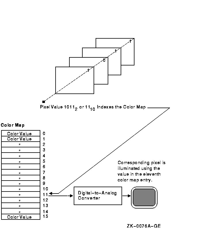
Xlib uses color maps to define the color of each pixel value. A color map contains a collection of color cells, each of which defines the color represented by a pixel value in terms of its red, green, and blue (RGB) components. Red, green, and blue components range from zero (off) to 65535 (brightest) inclusively. By combining the RGB components, many colors can be produced.
Each pixel value refers to a location in a color map or is an index into a color map. For example, the pixel value illustrated in Figure 5-1 indexes color cell 11 in Figure 5-2.
Figure 5-2 Color Map, Cell, and Index
Most color workstations have a hardware color map that translates pixel values into colors for the entire workstation screen. When the color definitions from a client's color map are stored in the hardware color map, that color map is said to be installed. If a client's color map is not installed, the client's windows will display in the wrong color.
For example, an image processing program that requires 128 colors might allocate and store a color map of these values. To alter some colors, another client may invoke a color palette program that chooses and mixes colors. The color palette program itself requires a color map, which the program allocates and installs.
Because both programs have allocated different color maps, undesirable results can be produced. The color palette image may be incorrectly displayed when the image processing program runs. The incorrect display results because only the image processing color map is installed. Conversely, when the color palette program runs, the image processing program may be incorrectly displayed because only the color palette color map is installed.
Xlib reduces the problem of contending for color resources in two ways:
- Xlib provides a default color map to which all clients have access.
- Clients can allocate either color cells for exclusive use or colors for shared use from the default color map.
By sharing colors, a client can use the same color cells as other clients. This method conserves space in the default color map.
In cases where the client cannot use the default color map and must use
a new color map, Xlib creates virtual color maps.
The use of virtual color maps is analogous to the use of virtual memory
in a multiprogramming environment where many processes must access
physical memory. When concurrent processes collectively require more
color map entries than exist in the hardware color map, the color
values are swapped in and out of the hardware color map. However,
swapping virtual color maps in and out of the hardware color map causes
contention for color resources. Therefore, the client should avoid
creating color maps whenever possible.
5.1.1 Installing Color Maps
The process of loading or unloading color values of the virtual color map into the hardware lookup table occurs when a client calls the INSTALL COLORMAP or UNINSTALL COLORMAP routine. Typically, the privilege to install or to remove color maps is restricted to the window manager. The window manager installs a color map when a window is given focus. The user gives a window focus by clicking on it with the mouse. The window manager then installs the color map for that window.
On a system with a single hardware color map, only one window can have color map focus at a time. Giving the focus to a new window will cause the previous window that had the focus to display in the wrong color.
Some systems provide multiple color maps in hardware. Multiple windows can have color map focus simultaneously. Each window, however, must be clicked on to install the correct color map and to get the correct colors.
Applications that have a window manager running should not make direct calls to install color maps. The window manager may reinstall different color maps if the client attempts to install a private color map. However, on a system with multiple color maps, the window manager will not remove the private color map. Thus, the client will display in correct colors without getting color map focus.
Applications that require subwindows to have color maps separate from
the top-level window can use the SET WM COLORMAP WINDOWS routine. This
routine provides a hint to the window manager to install the specified
color map. Normally, window managers install color maps only for the
top-level window. Some applications are designed to run without a
window manager. In this case, the application must issue requests to
install its own color map.
5.2 Matching Color Requirements to Display Types
The basic philosophy, when using color, is to determine the color needs of the client and then to determine how the system can best support those needs.
This section defines the different visual display types available and
describes methods to choose the appropriate type for the client.
5.2.1 Visual Types
Each screen has a list of visual types associated with it. The visual type identifies the characteristics of the screen, such as color or monochrome capability. Visual types partially determine the appearance of color on the screen and determine how a client can manipulate color maps for a specified screen.
Color maps can be manipulated in a variety of ways on some hardware, in a limited way on other hardware, and not at all on yet other hardware. For example, a screen may be able to display a full range of colors or a range of grays only, depending on its visual type.
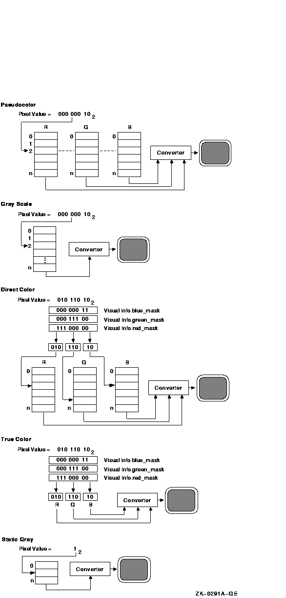
VMS DECwindows defines the following visual types:
- Pseudocolor
- Gray scale
- Direct color
- True color
- Static gray
- Static color
Pseudocolor is a full-color device. A pixel value indexes a color map composed of red, green, and blue definitions. Each definition in the color map stores the red, green, and blue component values for one color. The color index refers directly to a single entry in the color map. RGB values can be changed dynamically if a pixel has been allocated for exclusive use. Pseudocolor is the default visual type on Digital 4-plane and 8-plane systems.
In Figure 5-3, the pseudocolor illustration shows a pixel value of 2 (00000010 in binary) that indexes entry 2 in the color map.
Gray scale is a black and white device. Gray scale is the same as pseudocolor except that a pixel value indexes a color map that produces shades of gray only. The gray shades are defined in a color map with each definition having just one component that defines the level of the white intensity.
Refer to Figure 5-3 for an illustration of the gray scale visual type.
Direct color is a full-color device. Both the pixel value and the color map are separated into three independent parts, one each for red, green, and blue. The red part of the pixel indexes the red color map, the green indexes the green color map, and the blue indexes the blue color map. A complete color definition comprises the three components in each color map. RGB values can be changed dynamically if a pixel has been allocated for exclusive use.
In Figure 5-3, the direct color illustration shows that a pixel value of 90 (01011010 in binary) is separated into three values by using color masks, which are defined in the visual info data structure. (Refer to Section 5.2.3 for information about the visual info data structure.) Each color mask indicates which bits of the pixel value reference which color map. Each value is then used to index one of the three structures. In this case, entry 2 is indexed in the red color map, entry 6 in the green color map, and entry 2 in the blue color map.
True color is a full-color device. True color is the same as direct color except that the color map has predefined read-only RGB values in ascending order. True color is the default visual type on a Digital 24-plane system.
Refer to Figure 5-3 for an illustration of the true color visual type.
Static gray is a black and white device. Static gray is the same as gray scale except that the values in the color map are read-only. Static gray with a two-entry color map can be thought of as monochrome.
Refer to Figure 5-3 for an illustration of the static gray visual type.
Static color is a full-color device and is the same as pseudocolor except that the color map has predefined, read-only, server-dependent values in an undefined, server-dependent order.
Figure 5-3 Visual Types and Color Map Characteristics
5.2.2 Determining the Default Visual Type
Before defining colors, use the following method to determine the default visual type of a screen:
- Use the DEFAULT VISUAL OF SCREEN routine to determine the identifier of the visual. Xlib returns the identifier to a visual data structure.
- Refer to the class member of the data structure to determine the visual type.
The following example illustrates one method to determine the default visual type of a screen:
                         .
                         .
                         .
    if ((XDefaultVisualOfScreen(screen))->class == TrueColor
         ||  (XDefaultVisualOfScreen(screen))->class ==
              PseudoColor
         ||  (XDefaultVisualOfScreen(screen))->class ==
              DirectColor
         ||  (XDefaultVisualOfScreen(screen))->class ==
              StaticColor)
                         .
                         .
                         .
|
| Previous | Next | Contents | Index |