VMS DECwindows Guide to Xlib (Release 4)
Programming: MIT C Binding
Chapter 4
Defining Graphics Characteristics
After opening a display and creating a window, clients can draw lines
and shapes, create cursors, and draw text. Creating a graphics object
is a two-step process. Clients first define the characteristics of the
graphics object and then create it. For example, before creating a
line, a client first defines line width and style. After defining the
characteristics, the client creates the line with the specified width
and style.
This chapter describes how to define the graphics characteristics prior
to creating them, including the following topics:
- The graphics context (GC)---A description of the graphics
characteristics a client can define and the GC values data structure
used to define them
- Defining graphics characteristics---How to define graphics
characteristics using the CREATE GC routine
- Copying, changing, and freeing attributes---How to copy, change,
and undefine graphics characteristics
- Defining graphics characteristics efficiently---How to work
efficiently with several sets of graphics characteristics
Chapter 6 describes how to create graphics objects. Chapter 8
describes how to work with text.
4.1 The Graphics Context
The characteristics of a graphics object make up its graphics
context. As with window characteristics, Xlib provides a data
structure and routine to enable clients to define multiple graphics
characteristics easily. By setting values in the GC values data
structure and calling the CREATE GC routine, clients can define all
characteristics relevant to a graphics object.
Xlib also provides routines that enable clients to define individual or
functional groups of graphics characteristics.
Xlib always records the defined values in a GC data structure, which is
reserved for the use of Xlib and the server only. This occurs when
clients define graphic characteristics using either the CREATE GC
routine or one of the individual routines. Table 4-1 lists the
default values of the GC data structure.
Table 4-1 GC Data Structure Default Values
| Member Name |
Default Value |
|
Function
|
GXcopy
|
|
Plane mask
|
All ones
|
|
Foreground
|
0
|
|
Background
|
1
|
|
Line width
|
0
|
|
Line style
|
Solid
|
|
Cap style
|
Butt
|
|
Join style
|
Miter
|
|
Fill style
|
Solid
|
|
Fill rule
|
Even odd
|
|
Arc mode
|
Pie slice
|
|
Tile
|
Pixmap of unspecified size filled with foreground pixel
|
|
Stipple
|
Pixmap of unspecified size filled with ones
|
|
Tile or stipple x origin
|
0
|
|
Tile or stipple y origin
|
0
|
|
Font
|
Varies with implementation
|
|
Subwindow mode
|
Clip by children
|
|
Graphics exposures
|
True
|
|
Clip x origin
|
0
|
|
Clip y origin
|
0
|
|
Clip mask
|
None
|
|
Dash offset
|
0
|
|
Dashes
|
4 (the list [4,4])
|
4.2 Defining Multiple Graphics Characteristics in One Call
Xlib enables clients to define multiple characteristics of a graphics
object in one call. To define multiple characteristics, use the CREATE
GC routine as follows:
- Assign values to the relevant members of the GC values data
structure.
- Indicate the attributes to define by specifying the appropriate
flag in the value_mask argument of the routine. To
define more than one attribute, perform a bitwise OR on the appropriate
attribute flags.
The following illustrates the GC values data structure:
typedef struct {
        int function;
        unsigned long plane_mask;
        unsigned long foreground;
        unsigned long background;
        int line_width;
        int line_style;
        int cap_style;
        int join_style;
        int fill_style;
        int fill_rule;
        int arc_mode;
        Pixmap tile;
        Pixmap stipple;
        int ts_x_origin;
        int ts_y_origin;
        Font font;
        int subwindow_mode;
        Bool graphics_exposures;
        int clip_x_origin;
        int clip_y_origin;
        Pixmap clip_mask;
        int dash_offset;
        char dashes;
} XGCValues;
|
Table 4-2 describes the members of the data structure.
Table 4-2 GC Values Data Structure Members
| Member Name |
Contents |
|
function
|
Defines how the server computes pixel values when the client updates a
section of the screen.
|
|
plane_mask
|
Specifies the planes on which the server performs the bitwise
computation of pixels, defined by the function member.
|
|
foreground
|
Specifies an index to a color map entry for foreground color.
|
|
background
|
Specifies an index to a color map entry for background color.
|
|
line_width
|
Defines the width of a line in pixels.
Pixels with centers on a horizontal edge are a special case and are
part of the line if, and only if, the interior is immediately below the
bounding box (y increasing direction). See Figure 4-1.
|
|
line_style
|
Defines which sections of the line the server draws.
The following lists available line styles and the constants that
specify them.
| Constant Name |
Description |
|
LineSolid
|
The full path of the line is drawn.
|
|
LineDoubleDash
|
The full path of the line is drawn, but the even dashes are filled
differently than the odd dashes, with cap butt style used where even
and odd dashes meet.
|
|
LineOnOffDash
|
Only the even dashes are drawn. The cap_style member applies to all
internal ends of dashes. Specifying the constant CapNotLast is
equivalent to specifying CapButt.
|
Figure 4-2 illustrates the line styles.
|
|
cap_style
|
Defines how the server draws the endpoints of a path.
The following lists available cap styles and the constants that specify
them.
| Constant Name |
Description |
|
CapButt
|
Square at the endpoint (perpendicular to the slope of the line) with no
projection beyond the endpoint.
|
|
CapNotLast
|
Equivalent to CapButt, except that the final endpoint is not drawn if
the line width is zero or one.
|
|
CapRound
|
A circular arc with the diameter equal to the line width, centered on
the endpoint (equivalent to the value specified by CapButt for a line
width of zero or one).
|
|
CapProjecting
|
Square at the end, but the path continues beyond the endpoint for a
distance equal to half the width of the line (equivalent to the value
specified by the constant CapButt for a line width of zero or one).
|
Figure 4-3 illustrates the butt, round, and projecting cap styles. Figure 4-4 illustrates the style specified by the constant CapNotLast.
|
|
join_style
|
Defines how the server draws corners for wide lines.
Available join styles and the constants that specify them are as
follows.
| Constant Name |
Description |
|
JoinMiter
|
The outer edges of the two lines extend to meet at an angle
|
|
JoinRound
|
A circular arc with diameter equal to the line width, centered at the
join point
|
|
JoinBevel
|
Cap butt endpoint style, with the triangular notch filled
|
Figure 4-5 illustrates the join styles.
|
|
fill_style
|
Specifies the contents of the source for line, text, and fill
operations.
|
|
fill_rule
|
Defines what pixels the server draws along a path when a polygon is
filled (see Section 6.5.2).
The two available choices are EvenOddRule and WindingRule. The
EvenOddRule constant defines a point to be inside a polygon if an
infinite ray with the point as origin crosses the path an odd number of
times. If the point meets these conditions, the server draws a
corresponding pixel.
The WindingRule constant defines a point to be inside the polygon
if an infinite ray with the pixel as origin crosses an unequal number
of clockwise-directed and counterclockwise-directed path segments. A
clockwise-directed path segment is one that crosses the ray from left
to right as observed from the pixel. A counterclockwise-directed
segment is one that crosses the ray from right to left as observed from
that point. When a directed line segment coincides with a ray, choose a
different ray that is not coincident with a segment. If the point meets
these conditions, the server draws a corresponding pixel.
For both even/odd rule and winding rule, a point is infinitely
small and the path is an infinitely thin line. A pixel is inside the
polygon if the center point of the pixel is inside and the center point
is not on the boundary. If the center point is on the boundary, the
pixel is inside, if and only if, the polygon interior is immediately to
its right (x increasing direction). Pixels with centers along a
horizontal edge are a special case and are inside, if and only if, the
polygon interior is immediately below (y increasing direction).
Figure 4-6 illustrates fill rules. Figure 4-7 illustrates
rules for filling a pixel when it falls on a boundary.
|
|
arc_mode
|
Controls how the server fills an arc.
The available choices are the values specified by the ArcPieSlice and
ArcChord constants. Figure 4-8 illustrates the two modes.
|
|
tile
|
Specifies the pixmap that the server uses for tiling operations.
|
|
stipple
|
Specifies the pixmap that the server uses for stipple operations.
|
|
ts_x_origin
|
Defines the origin for tiling and stipple operations.
Origins are relative to the origin of whatever window or pixmap is
specified in the graphics request.
|
|
ts_y_origin
|
Defines the origin for tiling and stipple operations. Origins are
relative to the origin of whatever window or pixmap is specified in the
graphics request.
|
|
font
|
Specifies the font that the server uses for text operations.
|
|
subwindow_mode
|
Specifies whether or not inferior windows clip superior windows.
|
|
graphics_exposures
|
Specifies whether or not the server informs the client when the
contents of a window region are lost.
|
|
clip_x_origin
|
Defines the x-coordinate of the clip origin. The clip origin specifies
the point within the clip region that is aligned with the drawable
origin.
|
|
clip_y_origin
|
Defines the y-coordinate of the clip origin. The clip origin specifies
the point within the clip region that is aligned with the drawable
origin.
|
|
clip_mask
|
Identifies the pixmap that the server uses to restrict write operations
to the destination drawable.
When a client specifies the value of clip mask as None, the server
draws all pixels.
|
|
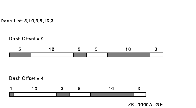
dash_offset
|
Specifies the pixel within the dash length sequence, defined by the
dashes member, to start drawing a dashed line.
For example, a dash offset of zero starts a dashed line as the
beginning of the dash line sequence. A dash offset of five starts the
line at the fifth pixel of the line sequence. Figure 4-9 illustrates
dashed offsets.
|
|
dashes
|
Specifies the length, in number of pixels, of each dash.
The value of this member must be nonzero or an error occurs.
|
Figure 4-1 illustrates how a bounding box affects line width.
Figure 4-1 Bounding Box
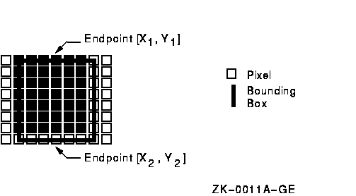
Figure 4-2 illustrates line styles.
Figure 4-2 Line Styles
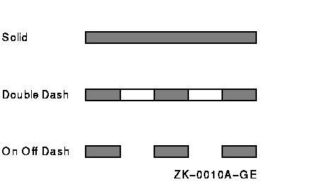
Figure 4-3 illustrates line cap styles.
Figure 4-3 Butt, Round, and Projecting Cap Styles
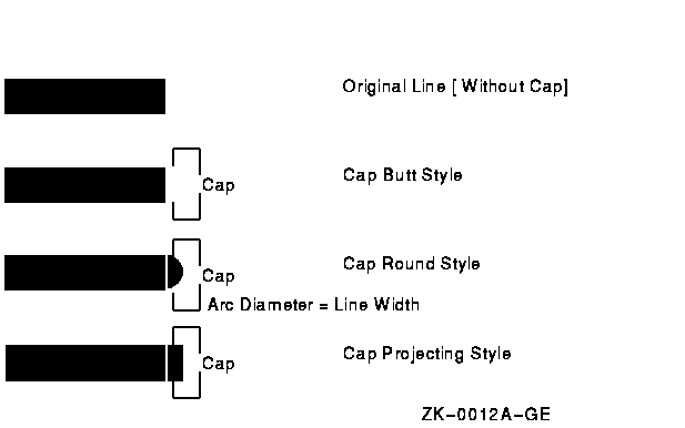
Figure 4-4 illustrates the line specified by the CapNotLast constant.
Figure 4-4 Cap Not Last Style

Figure 4-5 illustrates the join styles.
Figure 4-5 Join Styles
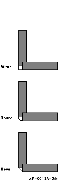
Figure 4-6 illustrates the fill rules.
Figure 4-6 Fill Rules
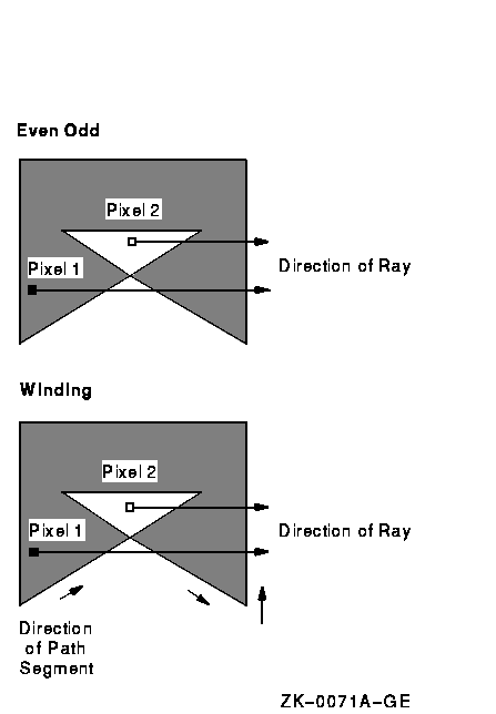
Figure 4-7 illustrates the rules for filling a pixel when it falls
on a boundary.
Figure 4-7 Pixel Boundary Cases
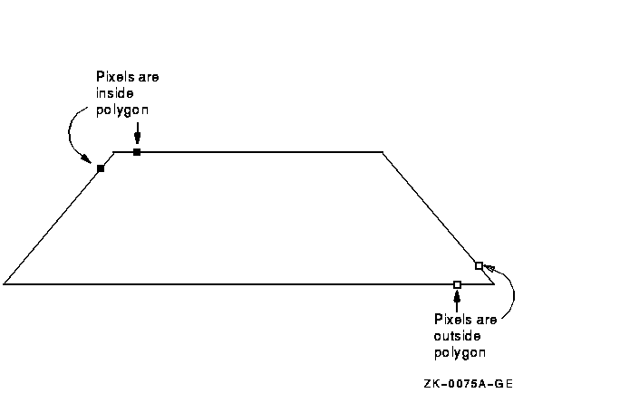
Figure 4-8 illustrates how an arc is filled.
Figure 4-8 Styles for Filling Arcs
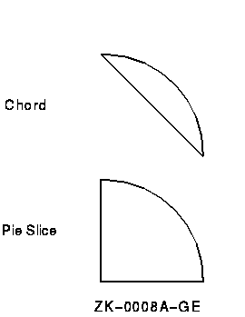
Figure 4-9 illustrates dash offsets.
Figure 4-9 Dashed Line Offset
Xlib assigns a flag for each member of the GC values data structure to
facilitate referring to members (Table 4-3).
Table 4-3 GC Values Data Structure Flags
| Flag Name |
GC Values Member |
|
GCFunction
|
function
|
|
GCPlaneMask
|
plane_mask
|
|
GCForeground
|
foreground
|
|
GCBackground
|
background
|
|
GCLineWidth
|
line_width
|
|
GCLineStyle
|
line_style
|
|
GCCapStyle
|
cap_style
|
|
GCJoinStyle
|
join_style
|
|
GCFillStyle
|
fill_style
|
|
GCFillRule
|
fill_rule
|
|
GCTile
|
tile
|
|
GCStipple
|
stipple
|
|
GCTileStipXOrigin
|
ts_x_origin
|
|
GCTileStipYOrigin
|
ts_y_origin
|
|
GCFont
|
font
|
|
GCSubwindowMode
|
subwindow_mode
|
|
GCGraphicsExposures
|
graphics_exposures
|
|
GCClipXOrigin
|
clip_x_origin
|
|
GCClipYOrigin
|
clip_y_origin
|
|
GCXClipMask
|
clip_mask
|
|
GCDashOffset
|
dash_offset
|
|
GCDashList
|
dash_list
|
|
GCArcMode
|
arc_mode
|
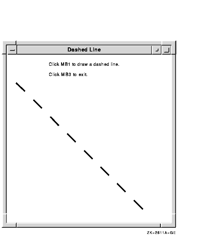
Example 4-1 illustrates how a client can define graphics context
values using the CREATE GC routine. Figure 4-10 shows the resulting
output.
| Example 4-1 Defining Graphics Characteristics
Using the CREATE GC Routine |
    /* Create window win on                               *
     *  display dpy, defined as follows:                  *
     *     Position: x = 100,y = 100                      *
     *     Width = 600                                    *
     *     Height = 600                                   *
     *  gc refers to the graphics context                 */
                    .
                    .
                    .

(1)GC gc;
                    .
                    .
                    .
static void doCreateGraphicsContext( )
{
(2)   XGCValues xgcv;

    /* Create graphics context. */

(3)  xgcv.foreground = doDefineColor(3);
    xgcv.background = doDefineColor(4);
    xgcv.line_width = 4;
    xgcv.line_style = LineDoubleDash;
    xgcv.dash_offset = 0;
    xgcv.dashes = 25;

(4)  gc = XCreateGC(dpy, win, GCForeground | GCBackground
        | GCLineWidth | GCLineStyle | GCDashOffset | GCDashList, &xgcv);
}
                    .
                    .
                    .
static void doButtonPress(eventP)
XEvent *eventP;
{
    x1 = y1 = 100;
    x2 = y2 = 550;

(5)  XDrawLine(dpy, win, gc, x1, y1, x2, y2);
}
|
- Assign storage for a graphics context (GC)
data structure. The scope of gc is global to enable windowing
and graphics routines in other modules to refer to it.
- Once the client defines characteristics with
the GC values data structure, Xlib does not have to refer to the data
structure again.
- Specify the foreground, background, line
width, line style, dash offset, and dashes for line drawing.
The
dashed line is four pixels wide. A dash offset value of zero starts
dashes at the beginning of the line. The dashes value, referred to by
GCDashList, specifies that dashes be 25 pixels long.
- The CREATE GC routine loads values into a GC
data structure. The CREATE GC routine has the following format:
gc_id = XCreateGC (display, drawable_id, gc_mask,
values_struc)
|
Indicate defined attributes with a bitwise OR that uses symbols
listed in Table 4-3.
- See Chapter 6 for information about
drawing lines.
Figure 4-10 Dashed Line
