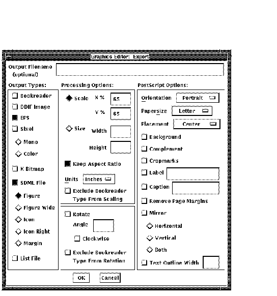
If you would like to see a printed copy of your workstation
drawing, print the PostScript file (WORKSTATION.EPS) on a PostScript
printer.
The SDML file that results looks like the following:
<comment>
This file was generated by DOCUMENT/GRAPHICS=RENDER with the
following commandline:
<endcomment>
<line>
DOCUMENT/GRAPHICS=RENDER /TYPE=(EPS,BRF) /SDML=FIGURE
/SCALE=(X=65,Y=65,EXCLUDE=BRF WORKSTATION.GRA
<FIGURE_FILE>(BOOKREADER\WORKSTATION.BRF\13.09)
<FIGURE_FILE>(LN03\SPACE\13.09)
<FIGURE_FILE>(LINE_PRINTER\SPACE\6.0)
<FIGURE_FILE>(PS\WORKSTATION.EPS\9.91)
|
Note
To share files with other users, copy them. Do not mail files
containing Graphics Editor graphics; mail often distorts the files or
does not send them.
|
Chapter 4
Working with Images and Capturing Screens
Images in the DECdocument Graphics Editor are bitonal, two-dimensional
grids of pixels (picture elements) referred to as bitmaps or pixmaps.
The pixels in the displayed image are arranged in rows and columns
coinciding with the dots of the workstation screen. They are either on
or off, typically meaning they are either black or white.
Image objects in the DECdocument Graphics Editor are obtained in one of
two ways:
- Imported from an external file
- Captured from the workstation screen
Images may be automatically created when a Version 8 GRA file is saved
to an older Version 5 file if the Version 8 file contains objects, such
as EPS objects, that are not identifiable to Version 5.
Images are distinct from object-oriented or structured graphics such as
lines, circles, arcs, and so on, in the following ways:
- Images are resolution dependent. Structured graphics elements are
resolution independent.
An image looks clearest when it is
displayed on a device with the same resolution (dots per inch) as the
device on which the image was created. The appearance of the structured
graphics components improves (the smoothness of angled lines, for
example) with increasing resolution of the rendering device.
- You cannot edit the contents of images; you cannot edit individual
elements of an image. For example, in a drawing of two chairs, one
chair is an image, and one chair is drawn using lines and arcs. The
image drawing of the chair can be scaled or moved and so on, but its
individual parts, such as a leg, cannot be changed. However, you can
edit the individual parts of the chair that was drawn using lines and
arcs.
This chapter explains how to:
- Display images on the screen (Section 4.1)
- Import an image (Section 4.2)
- Use Capture to capture screen images (Section 4.3)
- Use Capture ... to capture screen images (Section 4.4)
- How to crop images (Section 4.5)
For information on formatting and printing screens, see Chapter 3.
4.1 Using the Graphics Editor with Images
There are two menu items for working with images:
- Import ... on the File menu displays a stored image in the Drawing
window.
- Screen Capture on the View menu captures a portion of the screen
and creates an image of it.
4.2 Importing an Image
The Import ... menu item on the File menu lets you read in and display
an image in the Drawing window.
To import and display an image:
- Choose Import ... from the File menu. A File Selection dialog box
appears.
- Choose the type of image by clicking MB1 on the appropriate option
button.
- Enter the name of the file you want to display.
- Click MB1 on OK.
An extent rectangle the size of the image
appears in the Drawing window.
- Move the pointer to position the extent rectangle in the Drawing
window where you want the image to appear.
- Click MB2 to display the image. Each image you include is treated
as a separate object.
4.3 Using Screen Capture
The Screen Capture menu item on the View menu lets you capture and
digitize areas of your workstation screen. For example, you can capture
and digitize:
- Static screens, such as the main window of any product.
- Screens that require user interaction that you display by holding
down a mouse button such as a pull-down menu.
After capturing a screen, you can crop it or white out sections not
wanted, and save the image in several image file formats.
The Graphics Editor does not digitize colors. All colored images you
capture are converted to monochrome.
To capture the DECwindows Session Manager screen:
- Move the Graphics Editor and Session Manager windows so your screen
looks similar to Figure 4-1.
Figure 4-1 Capturing the Session Manager Screen
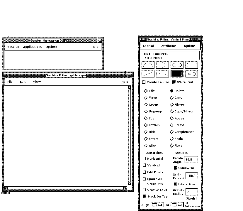
The window you are capturing (the Session Manager window) should
not be touching any other window. The Drawing window can overlap the
Control Panel. Only a small part of the Drawing window must be visible.
The left half of the Hints window should be visible.
- Choose Screen Capture from the View menu.
- Press the Do or Return key.
- Move the pointer to a corner of the Session Manager window.
- Hold down MB1 and draw a rectangle around the Session Manager
window. Before releasing MB1, use the arrow keys to position the
rectangle close to the edge of the window. Move the pointer to position
the two sides not affected by the arrow keys.
- Release MB1.
- Move the pointer to the Drawing window. Position the extent
rectangle so the right side of the rectangle is at the right side of
the Drawing window. The Drawing window should look similar to
Figure 4-2.
Figure 4-2 Displaying Captured Screen
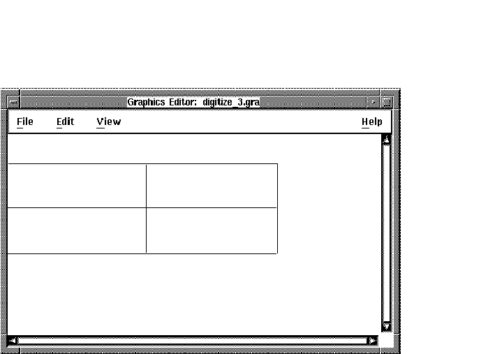
- Click MB2 to display the captured screen in the Drawing window.
- Resize the Drawing window to be slightly wider than the Session
Manager window you captured.
- Display the Pan Viewport submenu from the View menu, and choose
CENTER.
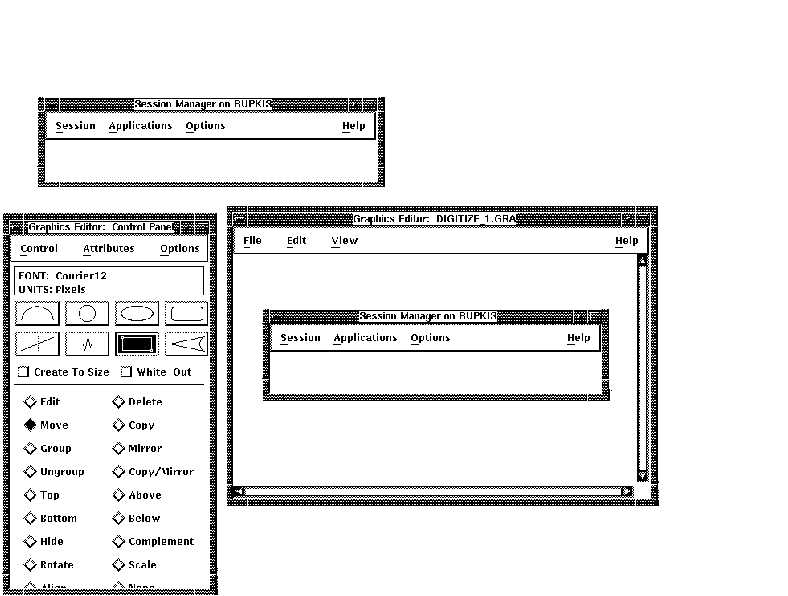
The Session Manager window you captured is centered in the
Drawing window. Your screen should look similar to Figure 4-3.
Figure 4-3 Centering a Captured Screen
- Choose Save As ... from the File menu.
- Enter EXAMPLE_1 in the Selection box of the Open dialog box. You
will use this image in a later exercise to learn how to crop an image.
4.4 Using Screen Capture ... to Capture Screens
The Screen Capture ... option lets you control the appearance of color
screens giving the resultant captured black and white image a more
accurate and realistic appearance.
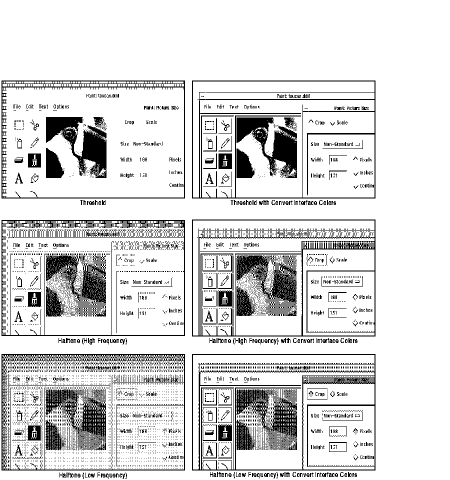
When you choose Screen Capture ... from the View menu, a dialog box
appears. Figure 4-4 shows the options on the dialog box,
Table 4-1 explains each of the four options, and Figure 4-5
shows a comparison of the results from the six possible option
combinations.
Note
The results of the Screen Capture operation varies with your choice of
customized interface colors.
|
Figure 4-4 Screen Capture ... Dialog Box

Table 4-1 Screen Capture ... Dialog Box Options
| Option |
Explanation |
|
Threshold
|
Colors in the captured image that have greater than 50 percent
luminance become white when printed or viewed. Colors in the captured
image that have fifty percent or less luminance become black when
printed or viewed.
|
Halftone
(High Frequency)
|
Simulates grey tones by using patterns of dots when the colors in the
image to be captured tend to be different from pixel to pixel; for
example, photographic-type or continuous tone images.
|
Halftone
(Low Frequency)
|
Simulates grey tones by using patterns of dots when the colors in the
image to be captured tend to be the same from pixel to pixel; for
example, when capturing application interfaces.
|
|
Convert Interface Colors
|
Converts the colors in the image to be captured to simulate the
appearance of a monochrome screen. This option is useful when capturing
application interfaces. Use this option with the Low Frequency Halftone
option.
|
Figure 4-5 Comparison of Screen Capture ... Options
To capture a dynamic menu, such as a pull-down menu for which you must
hold down MB1 to display, similar to capturing a static screen:
- Choose Screen Capture ... from the View menu. The Screen Capture
... dialog box appears.
- Click MB1 on Halftone (Low Frequency).
- Click MB1 on Convert Interface Colors.
- Click MB1 on OK. These options are selected until you reset them.
The pointer shape changes to a symbol of a finger pressing a key on a
keyboard.
- Display the Session Manager Customize menu.
- Press the Do key. The pointer shape changes to a crosshair.
- Hold down MB1 and draw an extent rectangle around the Customize
menu. Use the arrow keys to position the rectangle as close as possible
to the sides of the menu. Release MB1.
- Move the pointer to the Drawing window and position the extent
rectangle so the entire rectangle is displayed.
- Click MB2. The captured menu should resemble Figure 4-6.
Figure 4-6 Captured Menu

Any menu item you select when capturing a screen will be executed.
- Choose Save As ... from the File menu.
- Enter EXAMPLE_2. You will use this image in a later exercise to
learn how to crop the word Print from the image.
4.4.1 Redo Screen Capture
The Redo Screen Capture option lets you recapture the previously
captured area of the screen and place it into your drawing. Use this
option when you need to repeatedly capture the same area of the screen.
The Redo Screen Capture option uses the selected settings on the Screen
Capture ... dialog box.
Note
Redo Screen Capture uses a previously captured screen; therefore, you
must use Screen Capture or Screen Capture ... before you can use Redo
Screen Capture.
|
To use the Redo Screen Capture option:
- Use Screen Capture or Screen Capture ... to capture an image.
- Click MB1 on the Redo Screen Capture option on the View menu.
- The previously captured area of the screen is recaptured and placed
into your drawing in the exact location as the previous capture. If you
do not move the previous capture, the redigitized capture will be
layered ontop of it.
4.5 Cropping Images
There are two ways to delete unwanted objects or text from an image:
- Crop the image using the Revise option on the Control Panel
This works only if the region you want to keep is a rectangular
region. For example, when you captured the Session Manager window you
captured the entire window. If you want to crop off the top line of a
window, you can use this option to do so.
- Overwrite the unwanted object or text using an object in white out
mode.
You can use this method if you want to white-out information
in a captured screen that cannot be done with the Edit option. For
example, in the pull-down menu you captured, you will need to use this
method to obscure the word Print Screen.
To crop the top line off the image of the Session Manager screen you
captured:
- Choose Open ... from the File menu.
- Enter EXAMPLE_1 in the Open file selection box. See Figure 4-7.
Figure 4-7 Example 1 Cropping

- Choose the Revise option on the Control Panel.
- Select the image to be revised (cropped).
- Click MB2 to confirm the selection.
- Click MB1 and draw a rectangle around the image you want to keep
(all but the top line of the Session Manager screen). Use the arrow
keys and pointer to position the rectangle around the area you want to
keep.
- Click MB2 to confirm the selection.
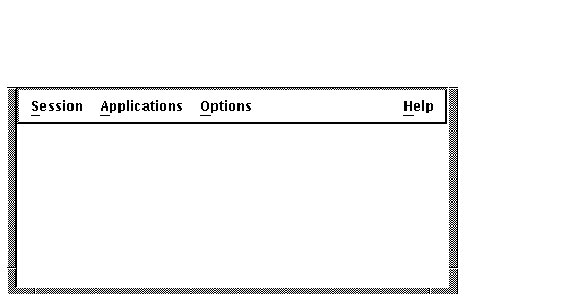
The top line of the
Session Manager screen is cropped off and will not appear on the screen
or in the saved file. The image should resemble Figure 4-8.
Figure 4-8 Example 1 Cropping
To recrop the original image:
- Redisplay the original image.
- With the Revise option selected, reselect the image.
- Click MB2 to confirm the selection. The original image before
cropping is redisplayed.
- Do one of the following:
- To create a new image crop box, repeat steps 6 and 7 in the
previous procedure.
- To keep the image at its original size before cropping and to
complete the crop operation, click MB2.
- To return the image to the last crop size and to complete the crop
operation, click MB3.
To white out the word Print at the top of the Customize pull-down menu
you captured:
- Choose Open ... from the File menu.
- Enter EXAMPLE_2 in the Open file selection box. The menu should
look like Figure 4-9.
Figure 4-9 Example 2 White Out

- Choose the Rectangle icon on the Control Panel.
- Turn on the White-Out option on the Control Panel.
- Turn on the Stack on Top option on the Control Panel.
- Draw a rectangle around the word Print. Use the arrow keys to
position the rectangle as close as possible to the area you want to
white out.
- Click MB2 to confirm the rectangle. A box the same color as your
background overlays the area you want deleted. The area whited out will
not appear on the screen or in the printed image.
If the box is
positioned incorrectly and you want to try again, use the Delete option
to delete the box and redraw another rectangle.
- Choose the Group option from the Control Panel and group the white
rectangle with the image, so they can be moved as one object.
The finished image should look similar to Figure 4-10.
Figure 4-10 Example 2 White-Out

