![[OpenVMS documentation]](../../images/openvms_doc_banner_top.gif)
|
![[Site home]](../../images/buttons/bn_site_home_off.gif)
![[Send comments]](../../images/buttons/bn_comments_off.gif)
![[Help with this site]](../../images/buttons/bn_site_help_off.gif)
![[How to order documentation]](../../images/buttons/bn_order_docs_off.gif)
![[OpenVMS site]](../../images/buttons/bn_openvms_off.gif)
![[Compaq site]](../../images/buttons/bn_compaq_off.gif)
|
| Updated: 11 December 1998 |
Guidelines for OpenVMS Cluster Configurations
| Previous | Contents | Index |
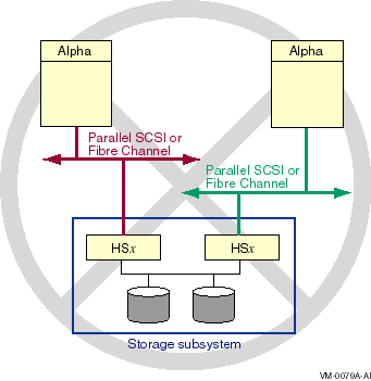
Figure 6-17 shows an invalid multipath configuration. The configuration is invalid because, if multiple hosts in a cluster are connected to an HSZ or HSG, they must all have connections to the same controller modules (see Table 6-1). In this configuration, each host is connected to a different controller module.
Figure 6-17 Invalid Multipath Configuration
6.8.3 Multipath System Parameters
Multipath support is enabled and qualified by the use of four system
parameters, as described in Table 6-3. (A fifth multipath system
parameter is reserved for the operating system.)
When OpenVMS Version 7.2 is released, the parameter MPDEV_REMOTE must remain set to the default value of OFF. This restriction will be removed by an update kit, shortly after the release of OpenVMS Version 7.2. |
| Parameter | Description |
|---|---|
| MPDEV_ENABLE | Enables the formation of multipath sets when set to ON (1). If set to OFF (0), the formation of additional multipath sets is disabled. However, existing multipath sets remain in effect. The default is ON. |
| MPDEV_LCRETRIES | Controls the number of times the system retries direct paths to the controller that the logical unit is online to, before moving on to direct paths to the other controller, or to an MSCP served path to the device. The valid range for retries is 1 through 256. The default is 1. |
| MPDEV_POLLER | Enables polling of the paths to multipath set members when set to ON (1). Polling allows early detection of errors on inactive paths. If a path becomes unavailable or returns to service, the system manager is notified with an OPCOM message. If set to OFF (0), multipath polling is disabled. The default is ON. |
| MPDEV_REMOTE | Enables MSCP served disks to become members of a multipath set when set to ON (1). If set to OFF (0), only local paths to a SCSI device will be used in the formation of additional multipath sets. However, setting this parameter to OFF will not have any effect on existing multipath sets that have remote paths. The default is OFF. |
| MPDEV_D1 | Reserved for use by the operating system. |
6.8.4 Path Identifiers
The system management commands described in the following sections
allow you to monitor and control the operation of multipath failover.
These commands provide a path identifier to uniquely specify each path
in a multipath set.
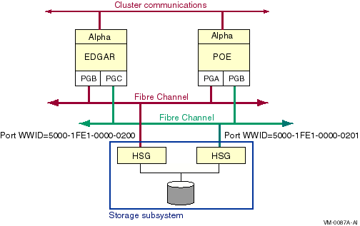
Direct Fibre Channel paths are identified by the local host adapter name and the remote Fibre Channel port WWID --- that is, the initiator and the target. For example, in Figure 6-18, the path identifier for the path from the host adapter on the left to the HSG storage controller on the left is PGB0.5000-1FE1-0000-0200. You can obtain the WWID for a storage controller from its console.
Figure 6-18 Fibre Channel Path Naming
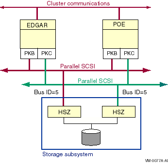
Direct parallel SCSI paths are identified by the local host adapter name and the remote SCSI bus ID --- that is, the initiator and the target. For example, in Figure 6-19, the path identifiers for node Edgar's two direct paths to the disk would be named PKB0.5 and PKC0.5.
The path identifier for MSCP served paths is MSCP.
Figure 6-19 Configuration With Multiple Direct Paths
When multipath support is enabled, you can display the multiple paths to a device using either of the following variants of the SHOW DEVICE DCL command:
SHOW DEVICE/FULL device-name SHOW DEVICE/MULTIPATH_SET device-name |
The SHOW DEVICE/FULL device-name command displays the traditional information about the device first and then lists all the paths to a device by their path identifiers (described in Section 6.8.4).
The SHOW DEVICE/MULTIPATH_SET device-name command lists only the multiple paths to a device.
6.8.5.1 Displaying Paths With SHOW DEVICE/FULL
The following example shows the output of a SHOW DEVICE/FULL
device-name command. Note that the use of multiple paths is
shown at the beginning of the display (device has multiple I/O
paths), and the multiple path descriptions are shown toward the
end of the display, beneath I/O paths to device. Note, too,
that the values for Error count and Operations
completed shown at the beginning of the display are the sums of
these counts for each path.
$ SHOW DEVICE/FULL $70$DKA100:

Disk $70$DKA100: (FLAM10), device type DEC HSZ70, is online, mounted, file-
    oriented device, shareable, device has multiple I/O paths, served to cluster
    via MSCP Server, error logging is enabled.

    Error count                    2    Operations completed             123471
    Owner process                 ""    Owner UIC                      [SYSTEM]
    Owner process ID        00000000    Dev Prot            S:RWPL,O:RWPL,G:R,W
    Reference count                1    Default buffer size                 512
    Total blocks             4109470    Sectors per track                    85
    Total cylinders             3022    Tracks per cylinder                  16
    Allocation class              70

    Volume label        "X6MV_SYS_1"    Relative volume number                0
    Cluster size                   9    Transaction count                     1
    Free blocks              2040228    Maximum files allowed            205524
    Extend quantity                5    Mount count                           4
    Mount status              System    Cache name        "_$600$DKA0:XQPCACHE"
    Extent cache size             64    Maximum blocks in extent cache   204022
    File ID cache size            64    Blocks currently in extent cache      0
    Quota cache size               0    Maximum buffers in FCP cache       2594
    Volume owner UIC           [1,1]    Vol Prot    S:RWCD,O:RWCD,G:RWCD,W:RWCD

  Volume Status:  ODS-2, subject to mount verification, file high-water marking,
      write-back caching enabled.
  Volume is also mounted on FIBRE3, COB2, FLAM10.

  I/O paths to device              2
  Path PKC0.1  (SISKO), primary path, current path.
    Error count                    1    Operations completed             121001
  Path PKB0.1  (SISKO).
    Error count                    1    Operations completed               2470
|
For each path of the multipath device, the path identifier, the host name associated with that path, the path status, the error count, and the operations count are displayed.
The terms that may appear in the multiple paths portion of the display are described in Table 6-4.
| Term | Description |
|---|---|
| Primary path | This was the first path to the device found by the operating system. |
| Current path | This path is currently used for I/O. |
| User disabled | The DCL command SET DEVICE/NOENABLE has been executed for this path. |
| Polling disabled | The DCL command SET DEVICE/NOPOLL has been executed for this path. |
| Unavailable | The path is unavailable because the software driver has disconnected from the path. |
| MSCP host unavailable | The path is unavailable because the connection to the MSCP server on the remote host has been broken. |
You can obtain a brief listing of multiple paths for a specific device, for all the devices in an allocation class, or for all devices with the DCL command:
SHOW DEVICE/MULTIPATH_SET [device-name] |
The device name is optional; when omitted, all devices that have formed multipath sets are shown. For each multipath device found, the device name, host name, device status, error count, number of accessible paths, total number of paths, and the current path's path identifier are displayed.
The host name displayed is the host name of the current path. For direct paths, this will be the local system's host name. For MSCP served paths, this will be the host name of the remote system which is serving access to the device.
The following example shows the output of a SHOW DEVICE /MULTIPATH command.
$ SHO DEV /MULTIPATH Device Device Error Current Name Status Count Paths path $70$DKA0: (FIBRE3) Online 0 3/ 3 PKB0.0 $70$DKA100: (FIBRE3) MountVerify 11 2/ 3 PKB0.1 $70$DKA200: (FIBRE3) Mounted 0 3/ 3 PKC0.2 $70$DKA300: (FIBRE3) Mounted 2 1/ 3 PKC0.3 $70$DKA400: (FIBRE3) Mounted 4 3/ 3 PKC0.4 $70$DKA500: (FIBRE3) Mounted 7 3/ 3 PKC0.5 $70$DKA1400: (FIBRE3) Mounted 0 3/ 3 PKC0.14 $70$DKA1500: (FIBRE3) Mounted 4 3/ 3 PKB0.15 $100$DKA100: (FIBRE3) Online 0 2/ 2 PKA0.1 $100$DKA200: (FIBRE3) Mounted 3 2/ 2 PKA0.2 $100$DKA300: (FIBRE3) Online 0 2/ 2 PKA0.3 $100$DKA400: (FIBRE3) Online wrtlck 0 2/ 2 PKA0.4 |
If you choose to specify a partial device name, such as $70$DKA, the display shows all devices with multiple paths whose names begin with $70$DKA.
6.8.6 Path Polling
When SCSI multipath support is in effect, the system periodically polls
all the I/O paths from each host adapter to each HSZ or HSG controller
to determine the status of each I/O path. If the system detects any
changes to a path, it outputs a message, similar to the following, to
the console and to the operator's log:
All multipath devices on path PKB0.5 are either disabled or not reachable. At least one multipath device on path PKB0.5 is enabled and reachable. |
If all the devices on a path are removed, a path failure is reported. The path from the host to the HSx controller may still function, but this cannot be determined when there are no devices to poll.
You can turn polling on or off with the following command:
SET DEVICE device/[NO]POLL/PATH=path-identifier |
Turning off polling for a path that will be out of service for a
prolonged period is useful because it can reduce system overhead.
6.8.7 Switching Current Paths Manually
You can switch a device's current path manually using the SET DEVICE command with the /SWITCH qualifier. The most common reason for doing this is to balance the aggregate I/O load across multiple HSx controller modules and buses.
The command syntax for switching the current path is:
SET DEVICE device-name/SWITCH/PATH=path-identifier |
The following command switches the path of device $2$DKA502 to an MSCP served path.
$ SET DEVICE $2$DKA502/SWITCH/PATH=MSCP |
By default all paths are candidates for path switching. You can disable or re-enable a path as a switch candidate by using the SET DEVICE command with the /[NO]ENABLE qualifier. The reasons you might want to do this include the following:
Note, the current path cannot be disabled.
The command syntax for enabling a disabled path is:
$ SET DEVICE device-name/[NO]ENABLE/PATH=path-identifier |
The following command enables the MSCP served path of device $2$DKA502.
$ SET DEVICE $2$DKA502/ENABLE/PATH=MSCP |
The following command disables a local path of device $2$DKA502.
$ SET DEVICE $2$DKA502/ENABLE/PATH=PKC0.5 |
Be careful when disabling paths. Avoid creating an invalid
configuration, such as the one shown in Figure 6-17
6.8.9 Console Considerations
The console uses traditional, path-dependent, SCSI device names. For example, the device name format for disks is DK, followed by a letter indicating the host adapter, followed by the SCSI target ID, and the LUN.
This means that a multipath device will have multiple names, one for each host adapter it is accessible through. In the following sample output of a console show device command, the console device name is in the left column. The middle column and the right column provide additional information, specific to the device type.
Notice, for example, that the devices dkb100 and dkc100 are really two paths to the same device. The name dkb100 is for the path through adapter PKB0, and the name dkc100 is for the path through adapter PKC0. This can be determined by referring to the middle column, where the informational name includes the HSZ allocation class. The HSZ allocation class allows you to determine which console "devices" are really paths to the same HSZ device.
The console may not recognize a change in the HSZ allocation class value until after you issue a console INIT command. |
>>>sho dev dkb0.0.0.12.0 $55$DKB0 HSZ70CCL XB26 dkb100.1.0.12.0 $55$DKB100 HSZ70 XB26 dkb104.1.0.12.0 $55$DKB104 HSZ70 XB26 dkb1300.13.0.12.0 $55$DKB1300 HSZ70 XB26 dkb1307.13.0.12.0 $55$DKB1307 HSZ70 XB26 dkb1400.14.0.12.0 $55$DKB1400 HSZ70 XB26 dkb1500.15.0.12.0 $55$DKB1500 HSZ70 XB26 dkb200.2.0.12.0 $55$DKB200 HSZ70 XB26 dkb205.2.0.12.0 $55$DKB205 HSZ70 XB26 dkb300.3.0.12.0 $55$DKB300 HSZ70 XB26 dkb400.4.0.12.0 $55$DKB400 HSZ70 XB26 dkc0.0.0.13.0 $55$DKC0 HSZ70CCL XB26 dkc100.1.0.13.0 $55$DKC100 HSZ70 XB26 dkc104.1.0.13.0 $55$DKC104 HSZ70 XB26 dkc1300.13.0.13.0 $55$DKC1300 HSZ70 XB26 dkc1307.13.0.13.0 $55$DKC1307 HSZ70 XB26 dkc1400.14.0.13.0 $55$DKC1400 HSZ70 XB26 dkc1500.15.0.13.0 $55$DKC1500 HSZ70 XB26 dkc200.2.0.13.0 $55$DKC200 HSZ70 XB26 dkc205.2.0.13.0 $55$DKC205 HSZ70 XB26 dkc300.3.0.13.0 $55$DKC300 HSZ70 XB26 dkc400.4.0.13.0 $55$DKC400 HSZ70 XB26 dva0.0.0.1000.0 DVA0 ewa0.0.0.11.0 EWA0 08-00-2B-E4-CF-0B pka0.7.0.6.0 PKA0 SCSI Bus ID 7 pkb0.7.0.12.0 PKB0 SCSI Bus ID 7 5.54 pkc0.7.0.13.0 PKC0 SCSI Bus ID 7 5.54 |
The console does not automatically attempt to use an alternate path to a device if I/O fails on the current path. For many console commands, however, it is possible to specify a list of devices that the console will attempt to access in order. In a multipath configuration, you can specify a list of console device names that correspond to the multiple paths of a device. For example, a boot command, such as the following, will cause the console to attempt to boot the multipath device through the DKB100 path first, and if that fails, it will attempt to boot through the DKC100 path:
BOOT DKB100, DKC100 |
To help you plan for the introduction of Fibre Channel in your computing environment, this documentation is provided in advance of the Fibre Channel functionality, which will be available shortly after the release of OpenVMS Version 7.2. |
A major benefit of OpenVMS is its support of a wide range of interconnects and protocols for network configurations and for OpenVMS Cluster System configurations. This chapter describes OpenVMS Alpha support for Fibre Channel as a storage interconnect for single systems and as a shared storage interconnect for multihost OpenVMS Cluster systems.
The following topics are discussed:
For information about multipath support for Fibre Channel configurations, see Chapter 6.
Note that the Fibre Channel and parallel SCSI interconnects are shown generically in the figures in this chapter. Each is represented as a horizontal line to which the node and storage subsystems are connected. Physically, the Fibre Channel interconnect is always radially wired from a switch, as shown in Figure 7-1. Parallel SCSI can be radially wired to a hub or can be a daisy-chained bus.
The representation of multiple SCSI disks and SCSI buses in a storage subsystem is also simplified. The multiple disks and SCSI buses, which one or more HSZx or HSGx controllers serve as a logical unit to a host, are shown in the figures as a single logical unit.
7.1 Overview of Fibre Channel
Fibre Channel is an ANSI standard network and storage interconnect that
offers many advantages over other interconnects. Its most important
features are described in Table 7-1.
| Feature | Description |
|---|---|
| High-speed transmission | 1.06 gigabits per second, full duplex, serial interconnect (can simultaneously transmit and receive 100 megabytes of data per second) |
| Choice of media | Initial OpenVMS support for fibre-optic media. Potential future support for copper media. |
| Long interconnect distances | Initial OpenVMS support for multimode fiber at 400 meters per link. Potential future support for 10 kilometer single-mode fiber links and 30 meter copper links. |
| Multiple protocols | Initial OpenVMS support for SCSI--3. Potential for IP, 802.3, HIPPI, ATM, IPI, and others in the future. |
| Numerous topologies | Initial OpenVMS support for switched FC (highly scalable, multiple concurrent communications). Potential future support for arbitrated loop (maximum number of nodes fixed at 126, shared bandwidth, hardware relatively inexpensive), fabric of switches, mixed arbitrated loop and switches, and point-to-point |
The initial OpenVMS implementation supports a single-switch topology, with multimode fiber-optic media, at distances up to 400 meters per link.
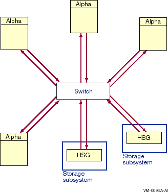
Figure 7-1 shows a logical view of a switched topology. The FC nodes are either Alpha hosts, or storage subsystems. Each link from a node to the switch is a dedicated FC connection. The switch provides store-and-forward packet delivery between pairs of nodes. Concurrent communication between disjoint pairs of nodes is supported by the switch.
Figure 7-1 Switched Topology, Logical View
A physical view of a Fibre Channel switched topology is shown in Figure 7-2.
Figure 7-2 Switched Topology, Physical View
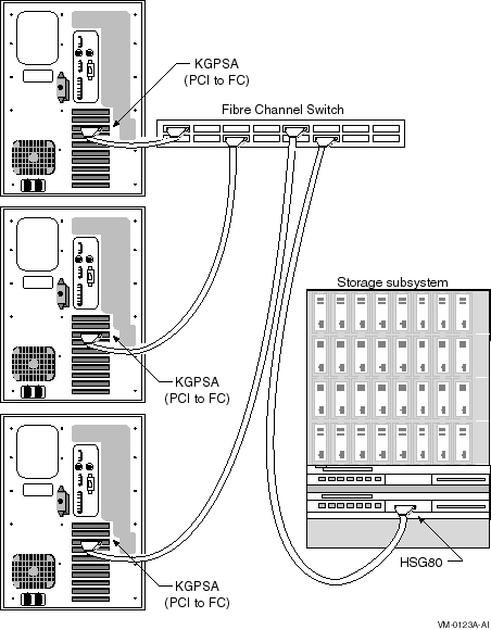
OpenVMS Alpha supports the Fibre Channel devices presented in Table 7-2. Fibre Channel hardware names typically use the letter G to designate hardware that is specific to Fibre Channel.
| Component Name | Description | Minimum Revision |
|---|---|---|
| AlphaServer 8400, 8200, 4100, 1200 1 | Alpha host | OpenVMS Version 7.2, FW Rev. 5.4 |
| HSG80 | Fibre Channel controller module; 1 or 2 can be used in a Fibre Channel RAID storage cabinet | FW Rev. 8.4 |
| KGPSA | OpenVMS Alpha PCI to Fibre Channel host adapter | FW Rev. TBD 2 |
| DSGGA | 16-port, multimode, Fibre Channel switch | FW Rev. TBD 2 |
| BNGBX- nn | Multimode fiber-optic cable ( nn denotes length in meters.) | n/a |
The following configurations are supported:
Note that many of the configuration limits, such as four Alpha hosts with four adapters each and two RAID storage cabinets per switch, were determined by the testing that was possible before this first release, not by the hardware or the Fibre Channel standards. OpenVMS plans to increase these limits in future releases.
| Previous | Next | Contents | Index |
![[Site home]](../../images/buttons/bn_site_home_off.gif)
![[Send comments]](../../images/buttons/bn_comments_off.gif)
![[Help with this site]](../../images/buttons/bn_site_help_off.gif)
![[How to order documentation]](../../images/buttons/bn_order_docs_off.gif)
![[OpenVMS site]](../../images/buttons/bn_openvms_off.gif)
![[Compaq site]](../../images/buttons/bn_compaq_off.gif)
|
![[OpenVMS documentation]](../../images/openvms_doc_banner_bottom.gif) |
|
Copyright © Compaq Computer Corporation 1998. All rights reserved. Legal |
6318PRO_007.HTML
|