![[OpenVMS documentation]](../../images/openvms_doc_banner_top.gif)
|
![[Site home]](../../images/buttons/bn_site_home_off.gif)
![[Send comments]](../../images/buttons/bn_comments_off.gif)
![[Help with this site]](../../images/buttons/bn_site_help_off.gif)
![[How to order documentation]](../../images/buttons/bn_order_docs_off.gif)
![[OpenVMS site]](../../images/buttons/bn_openvms_off.gif)
![[Compaq site]](../../images/buttons/bn_compaq_off.gif)
|
| Updated: 11 December 1998 |
|
|
|
|
| Updated: 11 December 1998 |
Guidelines for OpenVMS Cluster Configurations
| Previous | Contents | Index |
Figure 7-3 shows a single system using Fibre Channel as a storage interconnect.
Figure 7-3 Single System With Dual-Ported Storage Controllers
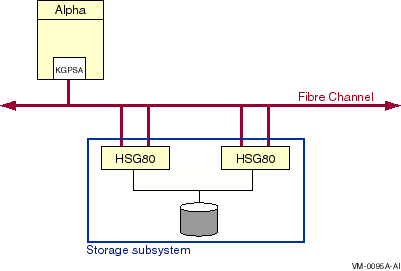
Note the following about this multipath configuration:
Figure 7-4 shows a multihost configuration with two independent Fibre Channel interconnects connecting the hosts to the storage subsystems.
Figure 7-4 Multihost Fibre Channel Configuration
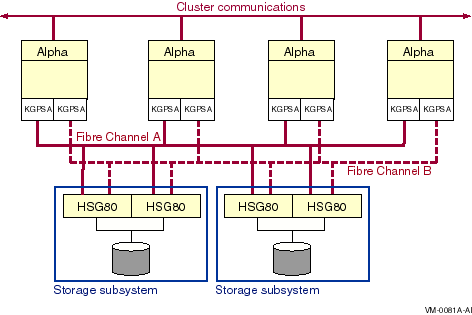
Note the following about this configuration:
The storage subsystems shown in Figure 7-4 are connected to two switches, which is the limit allowed in the initial Fibre Channel release. If additional host adapters and switches are desired, they must connect to additional RAID storage cabinets, as shown in Figure 7-5.
Figure 7-5 shows the largest configuration that is supported for the initial release of Fibre Channel.
Figure 7-5 Largest Initially Supported Configuration
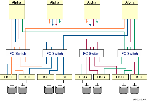
Note the following about this configuration:
Fibre Channel devices come with factory-assigned worldwide IDs (WWIDs). These WWIDs are used by the system for automatic FC address assignment. The FC WWIDs and addresses also provide the means for the system manager to identify and locate devices in the FC configuration. The FC WWIDs and adresses are displayed, for example, by the Alpha console and by the HSG80 console. It is necessary, therefore, for the system manager to understand the meaning of these identifiers and how they relate to OpenVMS device names.
7.4.1 Fibre Channel Addresses and WWIDs
In most situations, Fibre Channel devices are configured to have
temporary addresses. The device's address is assigned automatically
each time the interconnect initializes. The device may receive a new
address each time a Fibre Channel is reconfigured and reinitialized.
This is done so that Fibre Channel devices do not require the use of
address jumpers. There is one Fibre Channel address per port, as shown
in Figure 7-6.
Figure 7-6 Fibre Channel Host and Port Addresses
In order to provide more permanent identification, each port on each device has a WWID, which is assigned at the factory. Every Fibre Channel WWID is unique. Fibre Channel also has node WWIDs to identify multiported devices. WWIDs are used by the system to detect and recover from automatic address changes. They are useful to system managers for identifying and locating physical devices.
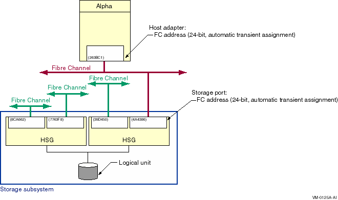
Figure 7-7 shows Fibre Channel components with their factory-assigned WWIDs and their Fibre Channel addresses.
Figure 7-7 Fibre Channel Host and Port WWIDs and Addresses
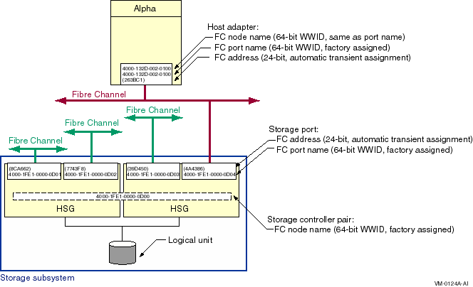
Note the following about this figure:
7.4.2 OpenVMS Names for Fibre Channel Devices
There is an OpenVMS name for each Fibre Channel storage adapter, for
each path from the storage adapter to the storage subsystem, and for
each storage device. These names are described in the following
sections.
7.4.2.1 Fibre Channel Storage Adapter Names
Fibre Channel storage adapter names, which are automatically assigned by OpenVMS, take the form FGx0:
The naming design places a limit of 26 adapters per system. (For the initial release, four adapters are supported per system.) This naming may be modified in future releases to support a larger number of adapters.
Fibre Channel adapters can run multiple protocols, such as SCSI and LAN. Each protocol is a pseudodevice associated with the adapter. For the initial implementation, just the SCSI protocol is supported. The SCSI pseudodevice name is PGx0, where x represents the same unit letter as the associated FGx0 adapter.
These names are illustrated in Figure 7-8.
Figure 7-8 Fibre Channel Initiator and Target Names
7.4.2.2 Fibre Channel Path Names
With the introduction of multipath SCSI support, as described in
Chapter 6, it is necessary to identify specific paths from the host
to the storage subsystem. This is done by concatenating the SCSI
pseudodevice name, a decimal point (.), and the WWID of the storage
subsystem port that is being accessed. For example, the Fibre Channel
path shown in Figure 7-8 is named PGB0.4000-1FE1-0000-0D04.
Refer to Chapter 6 for more information on the display and use of
the Fibre Channel path name.
7.4.2.3 Fibre Channel Storage Device Identification
The four identifiers associated with each FC storage device are shown in Figure 7-9.
Figure 7-9 Fibre Channel Storage Device Naming
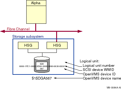
The logical unit number (LUN) is used by the system as the address of a specific device within the storage subsystem. This number is set and displayed from the HSG80 console by the system manager. It can also be displayed by the OpenVMS SDA utility.
Each Fibre Channel storage device also has a WWID to provide permanent, unique identification of the device. The HSG80 device WWID is 128 bits. Half of this identifier is the WWID of the HSG80 that created the logical storage device, and the other half is specific to the logical device. The device WWID is displayed by the HSG80 console and the AlphaServer console.
Fibre Channel device WWIDs are uniquely assigned to the device, and they are path independent, so they could be used for OpenVMS device naming, if they were not so long. For example, the Fibre Channel storage unit WWID shown in Figure 7-9 is: 6000-1FE1-0000-0D00-0009-8090-0630-0008.
To simplify the use of WWIDs in device names, OpenVMS enables the use of a shorter identifier, called an OpenVMS device ID. For the device with the WWID shown in Figure 7-9, a system manager might choose an OpenVMS device ID of 567.
An OpenVMS device ID for a Fibre Channel WWID has the following attributes:
A Fibre Channel storage device name is formed by the operating system from the constant $1$DGA and a device ID, nnnnn. The only variable part of the name is its device ID, which you assign at the HSG console. Figure 7-9 shows a storage device that is known to the host as $1$DGA567.
Availability is the percentage of time that a computing system provides application service. By taking advantage of OpenVMS Cluster features, you can configure your OpenVMS Cluster system for various levels of availability, including disaster tolerance.
This chapter provides strategies and sample optimal configurations for
building a highly available OpenVMS Cluster system. You can use these
strategies and examples to help you make choices and tradeoffs that
enable you to meet your availability requirements.
8.1 Availability Requirements
You can configure OpenVMS Cluster systems for different levels of availability, depending on your requirements. Most organizations fall into one of the broad (and sometimes overlapping) categories shown in Table 8-1.
| Availability Requirements | Description |
|---|---|
| Conventional | For business functions that can wait with little or no effect while a system or application is unavailable. |
| 24 x 365 | For business functions that require uninterrupted computing services, either during essential time periods or during most hours of the day throughout the year. Minimal down time is acceptable. |
| Disaster tolerant | For business functions with stringent availability requirements. These businesses need to be immune to disasters like earthquakes, floods, and power failures. |
OpenVMS Cluster systems offer the following features that provide increased availability:
In an OpenVMS Cluster environment, users and applications on multiple systems can transparently share storage devices and files. When you shut down one system, users can continue to access shared files and devices. You can share storage devices in two ways:
OpenVMS Cluster systems allow for redundancy of many components, including:
With redundant components, if one component fails, another is available
to users and applications.
8.2.3 Failover Mechanisms
OpenVMS Cluster systems provide failover mechanisms that enable recovery from a failure in part of the OpenVMS Cluster. Table 8-2 lists these mechanisms and the levels of recovery that they provide.
| Mechanism | What Happens if a Failure Occurs | Type of Recovery |
|---|---|---|
| DECnet--Plus cluster alias | If a node fails, OpenVMS Cluster software automatically distributes new incoming connections among other participating nodes. |
Manual. Users who were logged in to the failed node can reconnect to a
remaining node.
Automatic for appropriately coded applications. Such applications can reinstate a connection to the cluster alias node name, and the connection is directed to one of the remaining nodes. |
| I/O paths | With redundant paths to storage devices, if one path fails, OpenVMS Cluster software fails over to a working path, if one exists. | Transparent, provided another working path is available. |
| Interconnect | With redundant or mixed interconnects, OpenVMS Cluster software uses the fastest working path to connect to other OpenVMS Cluster members. If an interconnect path fails, OpenVMS Cluster software fails over to a working path, if one exists. | Transparent. |
| Boot and disk servers |
If you configure at least two nodes as boot and disk servers,
satellites can continue to boot and use disks if one of the servers
shuts down or fails.
Failure of a boot server does not affect nodes that have already booted, providing they have an alternate path to access MSCP served disks. |
Automatic. |
| Terminal servers and LAT software |
Attach terminals and printers to terminal servers. If a node fails, the
LAT software automatically connects to one of the remaining nodes. In
addition, if a user process is disconnected from a LAT terminal
session, when the user attempts to reconnect to a LAT session, LAT
software can automatically reconnect the user to the disconnected
session.
|
Manual. Terminal users who were logged in to the failed node must log in to a remaining node and restart the application. |
| Generic batch and print queues |
You can set up generic queues to feed jobs to execution queues (where
processing occurs) on more than one node. If one node fails, the
generic queue can continue to submit jobs to execution queues on
remaining nodes. In addition, batch jobs submitted using the /RESTART
qualifier are automatically restarted on one of the remaining nodes.
|
Transparent for jobs waiting to be dispatched.
Automatic or manual for jobs executing on the failed node. |
| Autostart batch and print queues | For maximum availability, you can set up execution queues as autostart queues with a failover list. When a node fails, an autostart execution queue and its jobs automatically fail over to the next logical node in the failover list and continue processing on another node. Autostart queues are especially useful for print queues directed to printers that are attached to terminal servers. | Transparent. |
Reference: For more information about cluster alias,
generic queues, and autostart queues, see OpenVMS Cluster Systems.
8.2.4 Related Software Products
Table 8-3 shows a variety of related OpenVMS Cluster software products that Compaq offers to increase availability.
| Product | Description |
|---|---|
| DECamds | Collects and analyzes data from multiple nodes simultaneously and directs all output to a centralized DECwindows display. The analysis detects availability problems and suggests corrective actions. |
| Volume Shadowing for OpenVMS | Makes any disk in an OpenVMS Cluster system a redundant twin of any other same-model disk in the OpenVMS Cluster. |
| DECevent | Simplifies disk monitoring. DECevent notifies you when it detects that a disk may fail. If the OpenVMS Cluster system is properly configured, DECevent can add a new disk and start a shadow copy operation. |
| POLYCENTER Console Manager (PCM) | Helps monitor OpenVMS Cluster operations. PCM provides a central location for coordinating and managing up to 24 console lines connected to OpenVMS nodes or HSJ/HSC console ports. |
The hardware you choose and the way you configure it has a significant
impact on the availability of your OpenVMS Cluster system. This section
presents strategies for designing an OpenVMS Cluster configuration that
promotes availability.
8.3.1 Availability Strategies
Table 8-4 lists strategies for configuring a highly available OpenVMS Cluster. These strategies are listed in order of importance, and many of them are illustrated in the sample optimal configurations shown in this chapter.
| Strategy | Description |
|---|---|
| Eliminate single points of failure | Make components redundant so that if one component fails, the other is available to take over. |
| Shadow system disks | The system disk is vital for node operation. Use Volume Shadowing for OpenVMS to make system disks redundant. |
| Shadow essential data disks | Use Volume Shadowing for OpenVMS to improve data availability by making data disks redundant. |
| Provide shared, direct access to storage | Where possible, give all nodes shared direct access to storage. This reduces dependency on MSCP server nodes for access to storage. |
| Minimize environmental risks |
Take the following steps to minimize the risk of environmental problems:
|
| Configure at least three nodes |
OpenVMS Cluster nodes require a quorum to continue operating. An
optimal configuration uses a minimum of three nodes so that if one node
becomes unavailable, the two remaining nodes maintain quorum and
continue processing.
Reference: For detailed information on quorum strategies, see Section 11.5 and OpenVMS Cluster Systems. |
| Configure extra capacity | For each component, configure at least one unit more than is necessary to handle capacity. Try to keep component use at 80% of capacity or less. For crucial components, keep resource use sufficiently less than 80% capacity so that if one component fails, the work load can be spread across remaining components without overloading them. |
| Keep a spare component on standby | For each component, keep one or two spares available and ready to use if a component fails. Be sure to test spare components regularly to make sure they work. More than one or two spare components increases complexity as well as the chance that the spare will not operate correctly when needed. |
| Use homogeneous nodes | Configure nodes of similar size and performance to avoid capacity overloads in case of failover. If a large node fails, a smaller node may not be able to handle the transferred work load. The resulting bottleneck may decrease OpenVMS Cluster performance. |
| Use reliable hardware | Consider the probability of a hardware device failing. Check product descriptions for MTBF (mean time between failures). In general, newer technologies are more reliable. |
Achieving high availability is an ongoing process. How you manage your
OpenVMS Cluster system is just as important as how you configure it.
This section presents strategies for maintaining availability in your
OpenVMS Cluster configuration.
8.4.1 Strategies for Maintaining Availability
After you have set up your initial configuration, follow the strategies listed in Table 8-5 to maintain availability in OpenVMS Cluster system.
| Strategy | Description |
|---|---|
| Plan a failover strategy |
OpenVMS Cluster systems provide software support for failover between
hardware components. Be aware of what failover capabilities are
available and which can be customized for your needs. Determine which
components must recover from failure, and make sure that components are
able to handle the additional work load that may result from a failover.
Reference: Table 8-2 lists OpenVMS Cluster failover mechanisms and the levels of recovery that they provide. |
| Code distributed applications | Code applications to run simultaneously on multiple nodes in an OpenVMS Cluster system. If a node fails, the remaining members of the OpenVMS Cluster system are still available and continue to access the disks, tapes, printers, and other peripheral devices that they need. |
| Minimize change | Assess carefully the need for any hardware or software change before implementing it on a running node. If you must make a change, test it in a noncritical environment before applying it to your production environment. |
| Reduce size and complexity | After you have achieved redundancy, reduce the number of components and the complexity of the configuration. A simple configuration minimizes the potential for user and operator errors as well as hardware and software errors. |
| Set polling timers identically on all nodes |
Certain system parameters control the polling timers used to maintain
an OpenVMS Cluster system. Make sure these system parameter values are
set identically on all OpenVMS Cluster member nodes.
Reference: For information about these system parameters, see OpenVMS Cluster Systems. |
| Manage proactively | The more experience your system managers have, the better. Allow privileges for only those users or operators who need them. Design strict policies for managing and securing the OpenVMS Cluster system. |
| Use AUTOGEN proactively | With regular AUTOGEN feedback, you can analyze resource usage that may affect system parameter settings. |
| Reduce dependencies on a single server or disk | Distributing data across several systems and disks prevents one system or disk from being a single point of failure. |
| Implement a backup strategy | Performing frequent backup procedures on a regular basis guarantees the ability to recover data after failures. None of the strategies listed in this table can take the place of a solid backup strategy. |
| Previous | Next | Contents | Index |
|
|
![[OpenVMS documentation]](../../images/openvms_doc_banner_bottom.gif) |
|
Copyright © Compaq Computer Corporation 1998. All rights reserved. Legal |
6318PRO_008.HTML
|