![[OpenVMS documentation]](../../images/openvms_doc_banner_top.gif)
|
![[Site home]](../../images/buttons/bn_site_home_off.gif)
![[Send comments]](../../images/buttons/bn_comments_off.gif)
![[Help with this site]](../../images/buttons/bn_site_help_off.gif)
![[How to order documentation]](../../images/buttons/bn_order_docs_off.gif)
![[OpenVMS site]](../../images/buttons/bn_openvms_off.gif)
![[Compaq site]](../../images/buttons/bn_compaq_off.gif)
|
| Updated: 11 December 1998 |
Guidelines for OpenVMS Cluster Configurations
| Previous | Contents | Index |
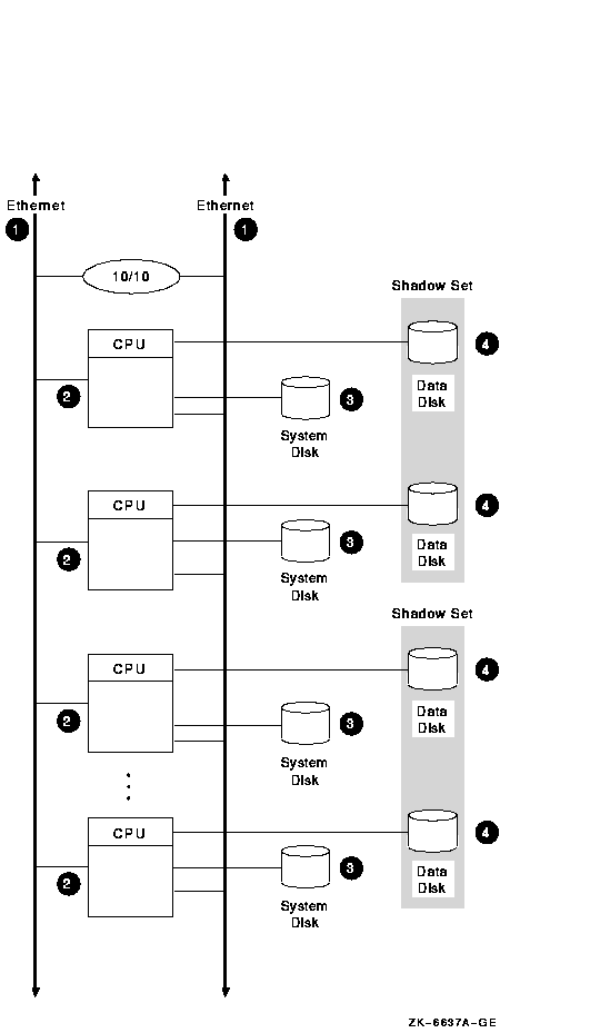
Figure 8-1 shows an optimal configuration for a small-capacity, highly available LAN OpenVMS Cluster system. Figure 8-1 is followed by an analysis of the configuration that includes:
Figure 8-1 LAN OpenVMS Cluster System
8.5.1 Components
The LAN OpenVMS Cluster configuration in Figure 8-1 has the
following components:
| Part | Description |
|---|---|
| 1 |
Two Ethernet interconnects. For higher network capacity, use FDDI
interconnects instead of Ethernet.
Rationale: For redundancy, use at least two LAN interconnects and attach all nodes to all LAN interconnects. A single interconnect would introduce a single point of failure. |
| 2 |
Three to eight Ethernet-capable OpenVMS nodes.
Each node has its own system disk so that it is not dependent on another node. Rationale: Use at least three nodes to maintain quorum. Use fewer than eight nodes to avoid the complexity of managing eight system disks. Alternative 1: If you require satellite nodes, configure one or two nodes as boot servers. Note, however, that the availability of the satellite nodes is dependent on the availability of the server nodes. Alternative 2: For more than eight nodes, use a LAN OpenVMS Cluster configuration as described in Section 8.10. |
| 3 |
System disks.
System disks generally are not shadowed in LAN OpenVMS Clusters because of boot-order dependencies. Alternative 1: Shadow the system disk across two local controllers. Alternative 2: Shadow the system disk across two nodes. The second node mounts the disk as a nonsystem disk. Reference: See Section 11.2.4 for an explanation of boot-order and satellite dependencies. |
| 4 |
Essential data disks.
Use volume shadowing to create multiple copies of all essential data disks. Place shadow set members on at least two nodes to eliminate a single point of failure. |
This configuration offers the following advantages:
This configuration has the following disadvantages:
The configuration in Figure 8-1 incorporates the following strategies, which are critical to its success:
Follow these guidelines to configure a highly available multiple LAN cluster:
Reference: See Section 10.7.7 for information about
extended LANs (ELANs).
8.6.1 Selecting MOP Servers
When using multiple LAN adapters with multiple LAN segments, distribute the connections to LAN segments that provide MOP service. The distribution allows MOP servers to downline load satellites even when network component failures occur.
It is important to ensure sufficient MOP servers for both VAX and Alpha nodes to provide downline load support for booting satellites. By careful selection of the LAN connection for each MOP server (Alpha or VAX, as appropriate) on the network, you can maintain MOP service in the face of network failures.
8.6.2 Configuring Two LAN Segments
Figure 8-2 shows a sample configuration for an OpenVMS Cluster
system connected to two different LAN segments. The configuration
includes Alpha and VAX nodes, satellites, and two bridges.
Figure 8-2 Two-LAN Segment OpenVMS Cluster Configuration
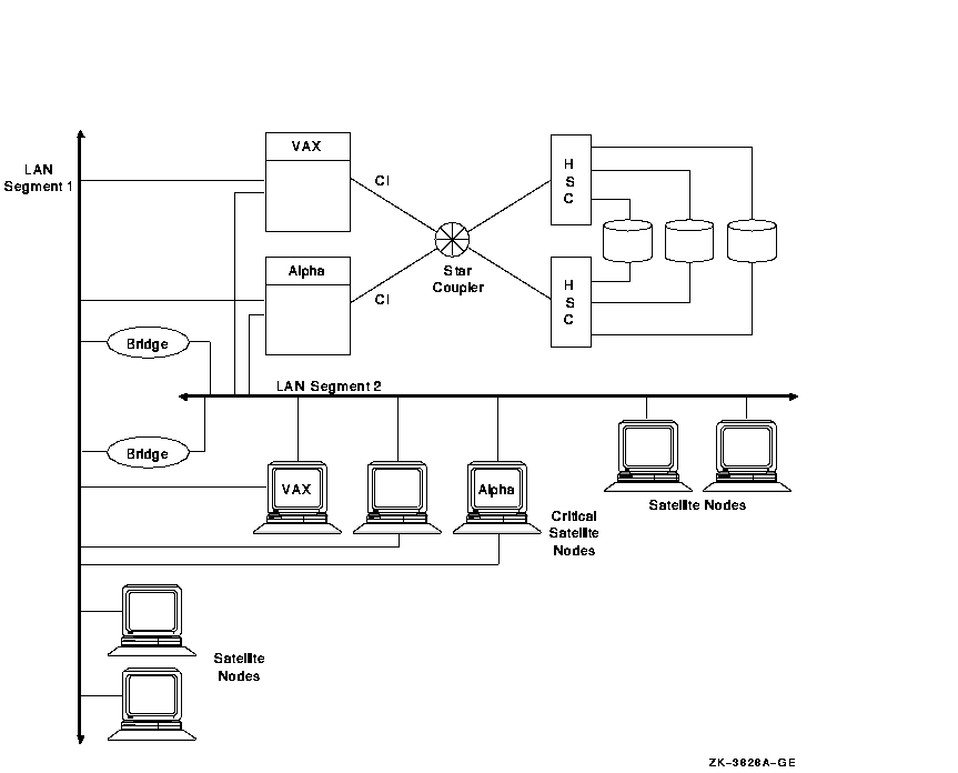
The figure illustrates the following points:
Figure 8-3 shows a sample configuration for an OpenVMS Cluster system connected to three different LAN segments. The configuration also includes both Alpha and VAX nodes and satellites and multiple bridges.
Figure 8-3 Three-LAN Segment OpenVMS Cluster Configuration
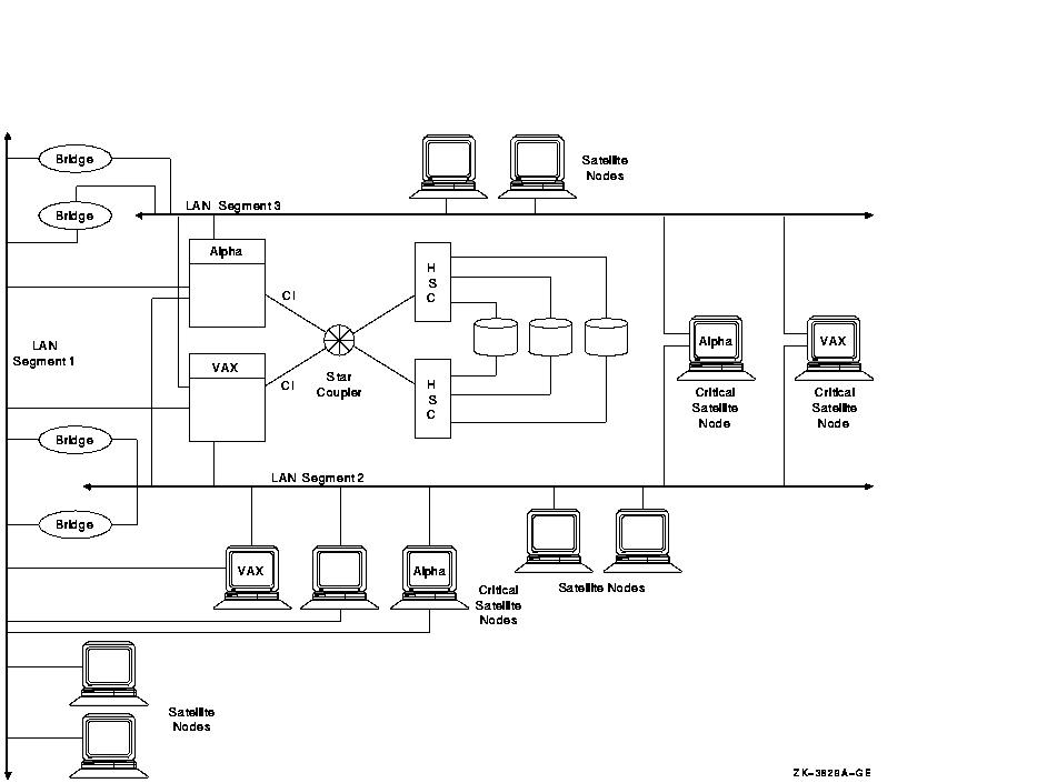
The figure illustrates the following points:
Reference: See Section 11.2.4 for more information
about boot order and satellite dependencies in a LAN. See OpenVMS Cluster Systems
for information about LAN bridge failover.
8.7 Availability in a DSSI OpenVMS Cluster
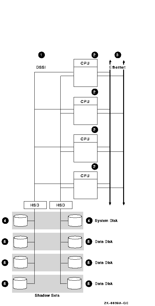
Figure 8-4 shows an optimal configuration for a medium-capacity, highly available DSSI OpenVMS Cluster system. Figure 8-4 is followed by an analysis of the configuration that includes:
Figure 8-4 DSSI OpenVMS Cluster System
8.7.1 Components
The DSSI OpenVMS Cluster configuration in Figure 8-4 has the
following components:
| Part | Description |
|---|---|
| 1 |
Two DSSI interconnects with two DSSI adapters per node.
Rationale: For redundancy, use at least two interconnects and attach all nodes to all DSSI interconnects. |
| 2 |
Two to four DSSI-capable OpenVMS nodes.
Rationale: Three nodes are recommended to maintain quorum. A DSSI interconnect can support a maximum of four OpenVMS nodes. Alternative 1: Two-node configurations require a quorum disk to maintain quorum if a node fails. Alternative 2: For more than four nodes, configure two DSSI sets of nodes connected by two LAN interconnects. |
| 3 |
Two Ethernet interconnects.
Rationale: The LAN interconnect is required for DECnet--Plus communication. Use two interconnects for redundancy. For higher network capacity, use FDDI instead of Ethernet. |
| 4 |
System disk.
Shadow the system disk across DSSI interconnects. Rationale: Shadow the system disk across interconnects so that the disk and the interconnect do not become single points of failure. |
| 5 |
Data disks.
Shadow essential data disks across DSSI interconnects. Rationale: Shadow the data disk across interconnects so that the disk and the interconnect do not become single points of failure. |
The configuration in Figure 8-4 offers the following advantages:
This configuration has the following disadvantages:
The configuration in Figure 8-4 incorporates the following strategies, which are critical to its success:
Figure 8-5 shows an optimal configuration for a large-capacity, highly available CI OpenVMS Cluster system. Figure 8-5 is followed by an analysis of the configuration that includes:
Figure 8-5 CI OpenVMS Cluster System
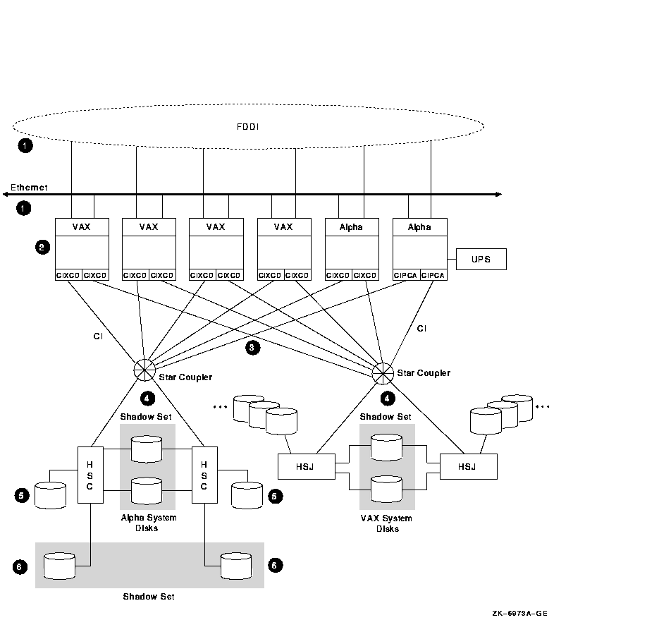
The CI OpenVMS Cluster configuration in Figure 8-5 has the following components:
| Part | Description |
|---|---|
| 1 |
Two LAN interconnects.
Rationale: The additional use of LAN interconnects is required for DECnet--Plus communication. Having two LAN interconnects---Ethernet or FDDI---increases redundancy. For higher network capacity, use FDDI instead of Ethernet. |
| 2 |
Two to 16 CI capable OpenVMS nodes.
Rationale: Three nodes are recommended to maintain quorum. A CI interconnect can support a maximum of 16 OpenVMS nodes. Reference: For more extensive information about the CIPCA, see Appendix C. Alternative: Two-node configurations require a quorum disk to maintain quorum if a node fails. |
| 3 |
Two CI interconnects with two star couplers.
Rationale: Use two star couplers to allow for redundant connections to each node. |
| 4 |
Critical disks are dual ported between CI storage controllers.
Rationale: Connect each disk to two controllers for redundancy. Shadow and dual port system disks between CI storage controllers. Periodically alternate the primary path of dual-ported disks to test hardware. |
| 5 |
Data disks.
Rationale: Single port nonessential data disks, for which the redundancy provided by dual porting is unnecessary. |
| 6 |
Essential data disks are shadowed across controllers.
Rationale: Shadow essential disks and place shadow set members on different HSCs to eliminate a single point of failure. |
This configuration offers the following advantages:
This configuration has the following disadvantage:
The configuration in Figure 8-5 incorporates the following strategies, which are critical to its success:
8.9 Availability in a MEMORY CHANNEL OpenVMS Cluster
Figure 8-6 shows a highly available MEMORY CHANNEL (MC) cluster
configuration. Figure 8-6 is followed by an analysis of the
configuration that includes:
Figure 8-6 MEMORY CHANNEL Cluster
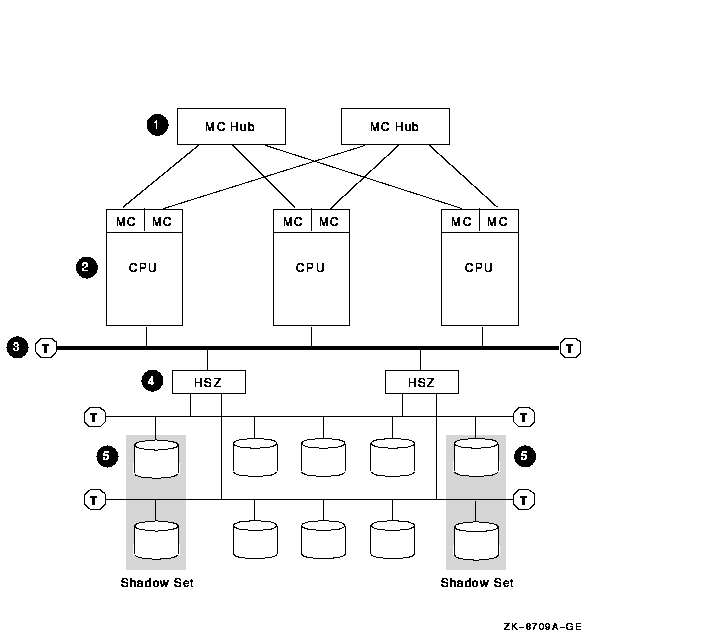
The MEMORY CHANNEL configuration shown in Figure 8-6 has the following components:
| Part | Description |
|---|---|
| 1 |
Two MEMORY CHANNEL hubs.
Rationale: Having two hubs and multiple connections to the nodes prevents having a single point of failure. |
| 2 |
Three to eight MEMORY CHANNEL nodes.
Rationale: Three nodes are recommended to maintain quorum. A MEMORY CHANNEL interconnect can support a maximum of eight OpenVMS Alpha nodes. Alternative: Two-node configurations require a quorum disk to maintain quorum if a node fails. |
| 3 |
Fast-wide differential (FWD) SCSI bus.
Rationale: Use a FWD SCSI bus to enhance data transfer rates (20 million transfers per second) and because it supports up to two HSZ controllers. |
| 4 |
Two HSZ controllers.
Rationale: Two HSZ controllers ensure redundancy in case one of the controllers fails. With two controllers, you can connect two single-ended SCSI buses and more storage. |
| 5 |
Essential system disks and data disks.
Rationale: Shadow essential disks and place shadow set members on different SCSI buses to eliminate a single point of failure. |
This configuration offers the following advantages:
This configuration has the following disadvantage:
The configuration in Figure 8-6 incorporates the following strategies, which are critical to its success:
Satellites are systems that do not have direct access to a system disk and other OpenVMS Cluster storage. Satellites are usually workstations, but they can be any OpenVMS Cluster node that is served storage by other nodes in the cluster.
Because satellite nodes are highly dependent on server nodes for availability, the sample configurations presented earlier in this chapter do not include satellite nodes. However, because satellite/server configurations provide important advantages, you may decide to trade off some availability to include satellite nodes in your configuration.
Figure 8-7 shows an optimal configuration for a OpenVMS Cluster system with satellites. Figure 8-7 is followed by an analysis of the configuration that includes:
The base configurations in Figure 8-4 and Figure 8-5 could replace the base configuration shown in Figure 8-7. In other words, the FDDI and satallite segments shown in Figure 8-7 could just as easily be attached to the configurations shown in Figure 8-4 and Figure 8-5.
Figure 8-7 OpenVMS Cluster with Satellites
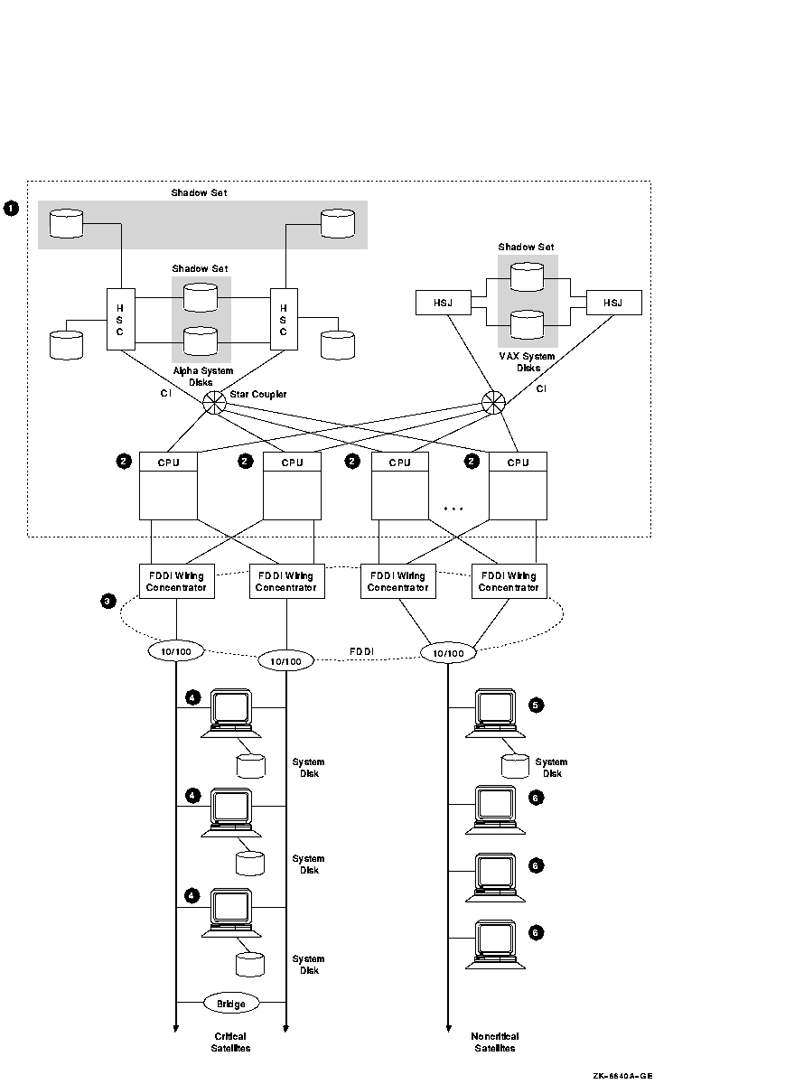
This satellite/server configuration in Figure 8-7 has the following components:
| Part | Description |
|---|---|
| 1 |
Base configuration.
The base configuration performs server functions for satellites. |
| 2 |
Three to 16 OpenVMS server nodes.
Rationale: At least three nodes are recommended to maintain quorum. More than 16 nodes introduces excessive complexity. |
| 3 |
FDDI ring between base server nodes and satellites.
Rationale: The FDDI ring has increased network capacity over Ethernet, which is slower. Alternative: Use two Ethernet segments instead of the FDDI ring. |
| 4 |
Two Ethernet segments from the FDDI ring to attach each critical
satellite with two Ethernet adapters. Each of these critical satellites
has its own system disk.
Rationale: Having their own boot disks increases the availability of the critical satellites. |
| 5 |
For noncritical satellites, place a boot server on the Ethernet segment.
Rationale: Noncritical satellites do not need their own boot disks. |
| 6 |
Limit the satellites to 15 per segment.
Rationale: More than 15 satellites on a segment may cause I/O congestion. |
This configuration provides the following advantages:
| Previous | Next | Contents | Index |
![[Site home]](../../images/buttons/bn_site_home_off.gif)
![[Send comments]](../../images/buttons/bn_comments_off.gif)
![[Help with this site]](../../images/buttons/bn_site_help_off.gif)
![[How to order documentation]](../../images/buttons/bn_order_docs_off.gif)
![[OpenVMS site]](../../images/buttons/bn_openvms_off.gif)
![[Compaq site]](../../images/buttons/bn_compaq_off.gif)
|
![[OpenVMS documentation]](../../images/openvms_doc_banner_bottom.gif) |
|
Copyright © Compaq Computer Corporation 1998. All rights reserved. Legal |
6318PRO_009.HTML
|