![[OpenVMS documentation]](../../images/openvms_doc_banner_top.gif)
|
![[Site home]](../../images/buttons/bn_site_home_off.gif)
![[Send comments]](../../images/buttons/bn_comments_off.gif)
![[Help with this site]](../../images/buttons/bn_site_help_off.gif)
![[How to order documentation]](../../images/buttons/bn_order_docs_off.gif)
![[OpenVMS site]](../../images/buttons/bn_openvms_off.gif)
![[Compaq site]](../../images/buttons/bn_compaq_off.gif)
|
| Updated: 11 December 1998 |
Guidelines for OpenVMS Cluster Configurations
| Previous | Contents | Index |
For CI-connected host systems, CIPCA is supported by any OpenVMS VAX host using CIXCD or CIBCA-B as well as by any OpenVMS Alpha server host using CIPCA or CIXCD. This means that an Alpha server using the CIPCA adapter can coexist on a CI bus with VAX systems using CIXCD and CIBCA-B CI adapters.
The maximum number of systems supported in an OpenVMS Cluster system,
96, is not affected by the use of one or more CIPCAs, although the
maximum number of CI nodes is limited to 16 (see Section C.3.4).
C.3.3 Storage Controller Support
The CIPCA adapter can coexist on a CI bus with all variants of the HSC/HSJ controllers except the HSC50. Certain controllers require specific firmware and hardware, as shown in Table C-3.
| Controller | Requirement |
|---|---|
| HSJ30, HSC40 | HSOF Version 2.5 (or higher) firmware |
| HSC40, HSC70 | Revision F (or higher) L109 module |
A CI star coupler expander (CISCE) can be added to any star coupler to
increase its connection capacity to 32 ports. The maximum number of
CPUs that can be connected to a star coupler is 16, regardless of the
number of ports.
C.3.5 Configuration Restrictions
Note the following configuration restrictions:
CIPCA-AA with EISA-Slot Link Module Rev. A01
For the CIPCA-AA adapter with the EISA-slot link module Rev. A01, use the DIP switch settings described here to prevent arbitration timeout errors. Under heavy CI loads, arbitration timeout errors can cause CI path errors and CI virtual circuit closures.
The DIP switch settings on the CIPCA-AA link module are used to specify cluster size and the node address. Follow these instructions when setting the DIP switches for link module Rev. A01 only:
These restrictions do not apply to the EISA slot link module Rev. B01 and higher or to the PCI-slot link module of the CIPCA-BA.
HSJ50 Firmware Requirement for Use of 4K CI Packets
Do not attempt to enable the use of 4K CI packets by the HSJ50
controller unless the HSJ50 firmware is Version 5.0J--3 or higher. If
the HSJ50 firmware version is less than Version 5.0J--3 and 4K CI
packets are enabled, data can become corrupted. If your HSJ50 firmware
does not meet this requirement, contact your Compaq support
representative.
C.4 Installation Requirements
When installing CIPCA adapters in your cluster, observe the following
version-specific requirements.
C.4.1 Managing Bus Addressable Pool (BAP) Size
The CIPCA, CIXCD, and KFMSB adapters use bus-addressable pool (BAP). Starting with OpenVMS Version 7.1, AUTOGEN controls the allocation of BAP. After installing or upgrading the operating system, you must run AUTOGEN with the FEEDBACK qualifier. When you run AUTOGEN in this way, the following four system parameters are set:
The BAP allocation amount depends on the adapter type, the number of adapters, and the version of the operating system. The size of physical memory determines whether the BAP remains separate or is merged with normal, nonpaged dynamic memory (NPAGEDYN), as shown in the following table:
| Adapter | Version 7.1 | Version 7.2 | Separate BAP or Merged |
|---|---|---|---|
| CIPCA | 4 MB | 2 MB | Separate if physical memory >1 GB; otherwise merged |
| CIXCD | 4 MB | 2 MB | Separate if physical memory >4 GB; otherwise merged |
| KFMSB | 8 MB | 4 MB | Separate if physical memory >4 GB; otherwise merged |
For systems whose BAP is merged with nonpaged pool, the initial amount and maximum amount of nonpaged pool (as displayed by the DCL command SHOW MEMORY/POOL/FULL) do not match the value of the SYSGEN parameters NPAGEDYN and NPAGEVIR. Instead, the value of SYSGEN parameter NPAG_BAP_MIN is added to NPAGEDYN to determine the initial size, and the value of NPAG_BAP_MAX is added to NPAGEVIR to determine the maximum size.
Your OpenVMS system may not require as much merged pool as the sum of
these SYSGEN parameters. After your system has been running a few days,
use AUTOGEN with the FEEDBACK qualifier to fine-tune the amount of
memory allocated for the merged, nonpaged pool.
C.4.2 AUTOCONFIGURE Restriction for OpenVMS Version 6.2-1H2 and OpenVMS Version 6.2-1H3
When you perform a normal installation boot, AUTOCONFIGURE runs
automatically. AUTOCONFIGURE is run from
SYS$STARTUP:VMS$DEVICE_STARTUP.COM (called from
SYS$SYSTEM:STARTUP.COM), unless disabled by SYSMAN. If you are running
OpenVMS Version 6.2-1H2 or OpenVMS Version 6.2-1H3 and you have
customized your booting sequence, make sure that AUTOCONFIGURE runs or
that you explicitly configure all CIPCA devices before
SYSTARTUP_VMS.COM exits.
C.5 DECevent for Analyzing CIPCA Errors
To analyze error log files for CIPCA errors, use DECevent. The DCL command ANALYZE/ERROR_LOG has not been updated to support CIPCA and other new devices; using that command will result in improperly formatted error log entries.
Install the DECevent kit supplied on the OpenVMS Alpha CD-ROM. Then use the following DCL commands to invoke DECevent to analyze dump files:
For more information about using DECevent, use the DCL HELP DIAGNOSE
command.
C.6 Performance Recommendations
To enhance performance, follow the recommendations that pertain to your
configuration.
C.6.1 Synchronous Arbitration
CIPCA uses a new, more optimal CI arbitration algorithm called synchronous arbitration instead of the older asynchronous arbitration algorithm. The two algorithms are completely compatible. Under CI saturation conditions, both the old and new algorithms are equivalent and provide equitable round-robin access to all nodes. However, with less traffic, the new algorithm provides the following benefits:
Support for synchronous arbitration is latent in the HSJ controller family. In configurations containing both CIPCAs and HSJ controllers, enabling the HSJs to use synchronous arbitration is recommended.
The HSJ CLI command to do this is:
CLI> SET THIS CI_ARB = SYNC |
This command will take effect upon the next reboot of the HSJ.
C.6.2 Maximizing CIPCA Performance With an HSJ50
To maximize the performance of the CIPCA adapter with an HSJ50 controller, it is advisable to enable the use of 4K CI packets by the HSJ50. To do this, your HSJ50 firmware revision level must be at Version 5.0J--3 or higher.
Do not attempt to do this if your HSJ50 firmware revision level is not Version 5.0J--3 or higher, because data can become corrupted. |
To enable the use of 4K CI packets, specify the following command at the HSJ50 console prompt:
CLI> SET THIS_CONTROLLER CI_4K_PACKET_CAPABILITY |
This command takes effect when the HSJ50 is rebooted.
This appendix describes multiple-site OpenVMS Cluster configurations in which multiple nodes are located at sites separated by relatively long distances, from approximately 25 to 125 miles, depending on the technology used. This configuration was introduced in OpenVMS Version 6.2. General configuration guidelines are provided and the three technologies for connecting multiple sites are discussed. The benefits of multiple site clusters are cited and pointers to additional documentation are provided.
The information in this appendix supersedes the Multiple-Site
VMScluster Systems addendum manual.
D.1 What is a Multiple-Site OpenVMS Cluster System?
A multiple-site OpenVMS Cluster system is an OpenVMS Cluster system in which the member nodes are located in geographically separate sites. Depending on the technology used, the distances can be as great as 150 miles.
When an organization has geographically dispersed sites, a multiple-site OpenVMS Cluster system allows the organization to realize the benefits of OpenVMS Cluster systems (for example, sharing data among sites while managing data center operations at a single, centralized location).
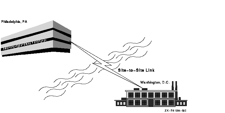
Figure D-1 illustrates the concept of a multiple-site OpenVMS Cluster system for a company with a manufacturing site located in Washington, D.C., and corporate headquarters in Philadelphia. This configuration spans a geographical distance of approximately 130 miles (210 km).
Figure D-1 Site-to-Site Link Between Philadelphia and Washington

The following link technologies between sites are approved for OpenVMS VAX and OpenVMS Alpha systems:
High-performance local area network (LAN) technology combined with the ATM, DS3, and FDDI interconnects allows you to utilize wide area network (WAN) communication services in your OpenVMS Cluster configuration. OpenVMS Cluster systems configured with the GIGAswitch crossbar switch and ATM, DS3, or FDDI interconnects approve the use of nodes located miles apart. (The actual distance between any two sites is determined by the physical intersite cable-route distance, and not the straight-line distance between the sites.) Section D.3 describes OpenVMS Cluster systems and the WAN communications services in more detail.
To gain the benefits of disaster tolerance across a multiple-site OpenVMS Cluster, use Disaster Tolerant Cluster Services for OpenVMS, a system management and software package from Compaq. Consult your Compaq Services representative for more information. |
Some of the benefits you can realize with a multiple-site OpenVMS Cluster system include the following:
| Benefit | Description |
|---|---|
| Remote satellites and nodes | A few systems can be remotely located at a secondary site and can benefit from centralized system management and other resources at the primary site, as shown in Figure D-2. For example, a main office data center could be linked to a warehouse or a small manufacturing site that could have a few local nodes with directly attached site-specific devices. Alternatively, some engineering workstations could be installed in an office park across the city from the primary business site. |
| Data center management consolidation | A single management team can manage nodes located in data centers at multiple sites. |
| Physical resource sharing | Multiple sites can readily share devices such as high-capacity computers, tape libraries, disk archives, or phototypesetters. |
| Remote archiving | Backups can be made to archival media at any site in the cluster. A common example would be to use disk or tape at a single site to back up the data for all sites in the multiple-site OpenVMS Cluster. Backups of data from remote sites can be made transparently (that is, without any intervention required at the remote site). |
| Increased availability |
In general, a multiple-site OpenVMS Cluster provides all of the
availability advantages of a LAN OpenVMS Cluster. Additionally, by
connecting multiple, geographically separate sites, multiple-site
OpenVMS Cluster configurations can increase the availability of a
system or elements of a system in a variety of ways:
|
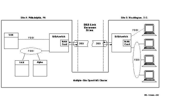
Figure D-2 shows an OpenVMS Cluster system with satellites accessible from a remote site.
Figure D-2 Multiple-Site OpenVMS Cluster Configuration with Remote Satellites

The same configuration rules that apply to OpenVMS Cluster systems on a LAN also apply to a multiple-site OpenVMS Cluster configuration that includes ATM, DS3, or FDDI intersite interconnect. General LAN configuration rules are stated in the following documentation:
Some configuration guidelines are unique to multiple-site OpenVMS
Clusters; these guidelines are described in Section D.3.4.
D.2 Using FDDI to Configure Multiple-Site OpenVMS Cluster Systems
Since VMS Version 5.4--3, FDDI has been the most common method to connect two distant OpenVMS Cluster sites. Using high-speed FDDI fiber-optic cables, you can connect sites with an intersite cable-route distance of up to 25 miles 40 km.3
You can connect sites using these FDDI methods:
Refer to the GIGAswitch/FDDI ATM Linecard Reference Manual for configuration information. Additional OpenVMS Cluster configuration guidelines and system management information can be found in this manual and in OpenVMS Cluster Systems. See the Overview of OpenVMS Documentation for information about ordering the current version of these manuals.
The inherent flexibility of OpenVMS Cluster systems and improved OpenVMS Cluster LAN protocols also allow you to connect multiple OpenVMS Cluster sites using the ATM or DS3 or both communications services.
3 The cable route distance between sites. |
D.3 Using WAN Services to Configure Multiple-Site OpenVMS Cluster Systems
This section provides an overview of the ATM and DS3 wide area network (WAN) services, describes how you can bridge an FDDI interconnect to the ATM or DS3 or both communications services, and provides guidelines for using these services to configure multiple-site OpenVMS Cluster systems.
The ATM and DS3 services provide long-distance, point-to-point communications that you can configure into your OpenVMS Cluster system to gain WAN connectivity. The ATM and DS3 services are available from most common telephone service carriers and other sources.
DS3 is not available in Europe and some other locations. Also, ATM is a new and evolving standard, and ATM services might not be available in all localities. |
ATM and DS3 services are approved for use with the following OpenVMS versions:
| Service | Approved Versions of OpenVMS |
|---|---|
| ATM | OpenVMS Version 6.2 or later |
| DS3 | OpenVMS Version 6.1 or later |
The following sections describe the ATM and DS3 communication services
and how to configure these services into multiple-site OpenVMS Cluster
systems.
D.3.1 The ATM Communications Service
The ATM communications service that uses the SONET physical layer (ATM/SONET) provides full-duplex communications (that is, the bit rate is available simultaneously in both directions as shown in Figure D-3). ATM/SONET is compatible with multiple standard bit rates. The SONET OC-3 service at 155 Mb/s full-duplex rate is the best match to FDDI's 100 Mb/s bit rate. ATM/SONET OC-3 is a standard service available in most parts of the world. In Europe, ATM/SONET is a high performance alternative to the older E3 standard.
Figure D-3 ATM/SONET OC-3 Service

To transmit data, ATM frames (packets) are broken into
cells for transmission by the ATM service. Each cell
has 53 bytes, of which 5 bytes are reserved for header information and
48 bytes are available for data. At the destination of the
transmission, the cells are reassembled into ATM frames. The use of
cells permits ATM suppliers to multiplex and demultiplex multiple data
streams efficiently at differing bit rates. This conversion of frames
into cells and back is transparent to higher layers.
D.3.2 The DS3 Communications Service (aka T3 Communications Service)
The DS3 communications service provides full-duplex communications as shown in Figure D-4. DS3 (also known as T3) provides the T3 standard bit rate of 45 Mb/s. T3 is the standard service available in North America and many other parts of the world.
Figure D-4 DS3 Service

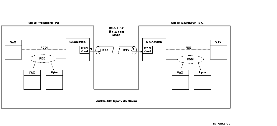
You can use FDDI-to-WAN (for example, FDDI-to-ATM or FDDI-to-DS3 or both) bridges to configure an OpenVMS Cluster with nodes in geographically separate sites, such as the one shown in Figure D-5. In this figure, the OpenVMS Cluster nodes at each site communicate as though the two sites are connected by FDDI. The FDDI-to-WAN bridges make the existence of ATM and DS3 transparent to the OpenVMS Cluster software.
Figure D-5 Multiple-Site OpenVMS Cluster Configuration Connected by DS3

In Figure D-5, the FDDI-to-DS3 bridges and DS3 operate as follows:
Compaq recommends using the GIGAswitch/FDDI system to construct
FDDI-to-WAN bridges. The GIGAswitch/FDDI, combined with the DEFGT WAN
T3/SONET option card, was used during qualification testing of the ATM
and DS3 communications services in multiple-site OpenVMS Cluster
systems.
D.3.4 Guidelines for Configuring ATM and DS3 in an OpenVMS Cluster System
When configuring a multiple-site OpenVMS Cluster, you must ensure that
the intersite link's delay, bandwidth, availability, and bit error rate
characteristics meet application needs. This section describes the
requirements and provides recommendations for meeting those
requirements.
D.3.4.1 Requirements
To be a configuration approved by Compaq, a multiple-site OpenVMS Cluster must comply with the following rules:
| Maximum intersite link route distance |
The total intersite link cable route distance between members of a
multiple-site OpenVMS Cluster cannot exceed 150 miles (242 km). You can
obtain exact distance measurements from your ATM or DS3 supplier.
This distance restriction can be exceeded when using Disaster Tolerant Cluster Services for OpenVMS, a system management and software package for configuring and managing OpenVMS disaster tolerant clusters. |
| Maximum intersite link utilization | Average intersite link utilization in either direction must be less than 80% of the link's bandwidth in that direction for any 10-second interval. Exceeding this utilization is likely to result in intolerable queuing delays or packet loss. |
| Intersite link specifications | The intersite link must meet the OpenVMS Cluster requirements specified in Table D-3. |
| OpenVMS Cluster LAN configuration rules | Apply the configuration rules for OpenVMS Cluster systems on a LAN to a configuration. Documents describing configuration rules are referenced in Section D.1.3. |
| Previous | Next | Contents | Index |
![[Site home]](../../images/buttons/bn_site_home_off.gif)
![[Send comments]](../../images/buttons/bn_comments_off.gif)
![[Help with this site]](../../images/buttons/bn_site_help_off.gif)
![[How to order documentation]](../../images/buttons/bn_order_docs_off.gif)
![[OpenVMS site]](../../images/buttons/bn_openvms_off.gif)
![[Compaq site]](../../images/buttons/bn_compaq_off.gif)
|
![[OpenVMS documentation]](../../images/openvms_doc_banner_bottom.gif) |
|
Copyright © Compaq Computer Corporation 1998. All rights reserved. Legal |
6318PRO_021.HTML
|