![[Compaq]](../../images/compaq.gif)
![[Go to the documentation home page]](../../images/buttons/bn_site_home.gif)
![[How to order documentation]](../../images/buttons/bn_order_docs.gif)
![[Help on this site]](../../images/buttons/bn_site_help.gif)
![[How to contact us]](../../images/buttons/bn_comments.gif)
![[OpenVMS documentation]](../../images/ovmsdoc_sec_head.gif)
| Document revision date: 19 July 1999 | |
![[Compaq]](../../images/compaq.gif) |
![[Go to the documentation home page]](../../images/buttons/bn_site_home.gif)
![[How to order documentation]](../../images/buttons/bn_order_docs.gif)
![[Help on this site]](../../images/buttons/bn_site_help.gif)
![[How to contact us]](../../images/buttons/bn_comments.gif)
|
![[OpenVMS documentation]](../../images/ovmsdoc_sec_head.gif)
|
|
| Previous | Contents | Index |
Each CI star coupler can have up to 32 nodes attached; 16 can be
systems and the rest can be storage controllers and storage.
Figure 10-2, Figure 10-3, and Figure 10-4 show a progression from
a two-node CI OpenVMS Cluster to a seven-node CI OpenVMS Cluster.
10.3.1 Two-Node CI OpenVMS Cluster
In Figure 10-2, two nodes have shared, direct access to storage that includes a quorum disk. The VAX and Alpha systems each have their own system disks.
Figure 10-2 Two-Node CI OpenVMS Cluster
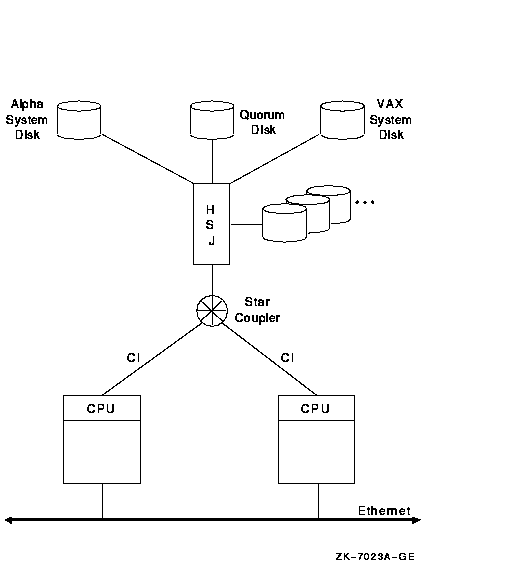
The advantages and disadvantages of the configuration shown in Figure 10-2 include:
An increased need for more storage or processing resources could lead
to an OpenVMS Cluster configuration like the one shown in Figure 10-3.
10.3.2 Three-Node CI OpenVMS Cluster
In Figure 10-3, three nodes are connected to two HSC controllers by the CI interconnects. The critical system disk is dual ported and shadowed.
Figure 10-3 Three-Node CI OpenVMS Cluster
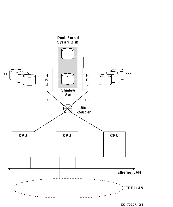
The advantages and disadvantages of the configuration shown in Figure 10-3 include:
If the I/O activity exceeds the capacity of the CI interconnect, this
could lead to an OpenVMS Cluster configuration like the one shown in
Figure 10-4.
10.3.3 Seven-Node CI OpenVMS Cluster
In Figure 10-4, seven nodes each have a direct connection to two star couplers and to all storage.
Figure 10-4 Seven-Node CI OpenVMS Cluster
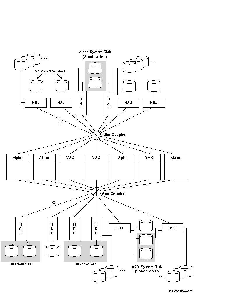
The advantages and disadvantages of the configuration shown in Figure 10-4 include:
The following guidelines can help you configure your CI OpenVMS Cluster:
Volume shadowing is intended to enhance availability, not performance. However, the following volume shadowing strategies enable you to utilize availability features while also maximizing I/O capacity. These examples show CI configurations, but they apply to DSSI and SCSI configurations, as well.
Figure 10-5 Volume Shadowing on a Single Controller
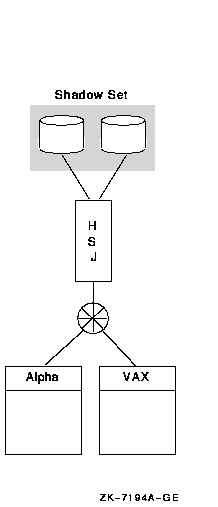
Figure 10-5 shows two nodes connected to an HSJ, with a two-member shadow set.
The disadvantage of this strategy is that the controller is a single point of failure. The configuration in Figure 10-6 shows examples of shadowing across controllers, which prevents one controller from being a single point of failure. Shadowing across HSJ and HSC controllers provides optimal scalability and availability within an OpenVMS Cluster system.
Figure 10-6 Volume Shadowing Across Controllers
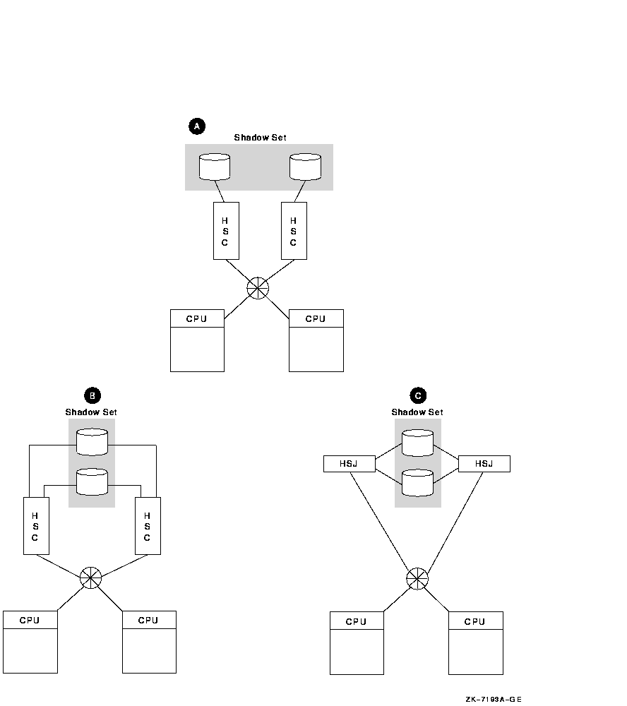
As Figure 10-6 shows, shadowing across controllers has three variations:
Figure 10-7 shows an example of shadowing across nodes.
Figure 10-7 Volume Shadowing Across Nodes
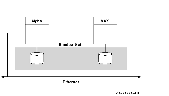
As Figure 10-7 shows, shadowing across nodes provides the advantage of flexibility in distance. However, it requires MSCP server overhead for write I/Os. In addition, the failure of one of the nodes and its subsequent return to the OpenVMS Cluster will cause a copy operation.
If you have multiple volumes, shadowing inside a controller and shadowing across controllers are more effective than shadowing across nodes.
Reference: See Volume Shadowing for OpenVMS for more information.
10.4 Scalability in DSSI OpenVMS Clusters
Each DSSI interconnect can have up to eight nodes attached; four can be
systems and the rest can be storage devices. Figure 10-8,
Figure 10-9, and Figure 10-10 show a progression from a two-node
DSSI OpenVMS Cluster to a four-node DSSI OpenVMS Cluster.
10.4.1 Two-Node DSSI OpenVMS Cluster
In Figure 10-8, two nodes are connected to four disks by a common DSSI interconnect.
Figure 10-8 Two-Node DSSI OpenVMS Cluster
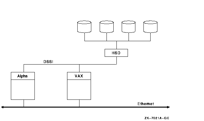
The advantages and disadvantages of the configuration shown in Figure 10-8 include:
If the OpenVMS Cluster in Figure 10-8 required more processing power,
more storage, and better redundancy, this could lead to a configuration
like the one shown in Figure 10-9.
10.4.2 Four-Node DSSI OpenVMS Cluster with Shared Access
In Figure 10-9, four nodes have shared, direct access to eight disks through two DSSI interconnects. Two of the disks are shadowed across DSSI interconnects.
Figure 10-9 Four-Node DSSI OpenVMS Cluster with Shared Access
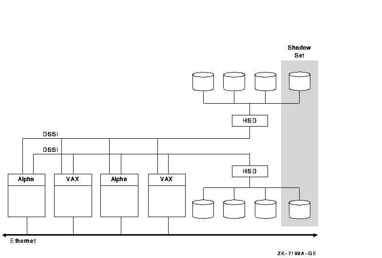
The advantages and disadvantages of the configuration shown in Figure 10-9 include:
If the configuration in Figure 10-9 required more storage, this could
lead to a configuration like the one shown in Figure 10-10.
10.4.3 Four-Node DSSI OpenVMS Cluster with Some Nonshared Access
Figure 10-10 shows an OpenVMS Cluster with 4 nodes and 10 disks. This model differs from Figure 10-8 and Figure 10-9 in that some of the nodes do not have shared, direct access to some of the disks, thus requiring these disks to MSCP served. For the best performance, place your highest-priority data on disks that are directly connected by common DSSI interconnects to your nodes. Volume shadowing across common DSSI interconnects provides the highest availability and may increase read performance.
Figure 10-10 DSSI OpenVMS Cluster with 10 Disks
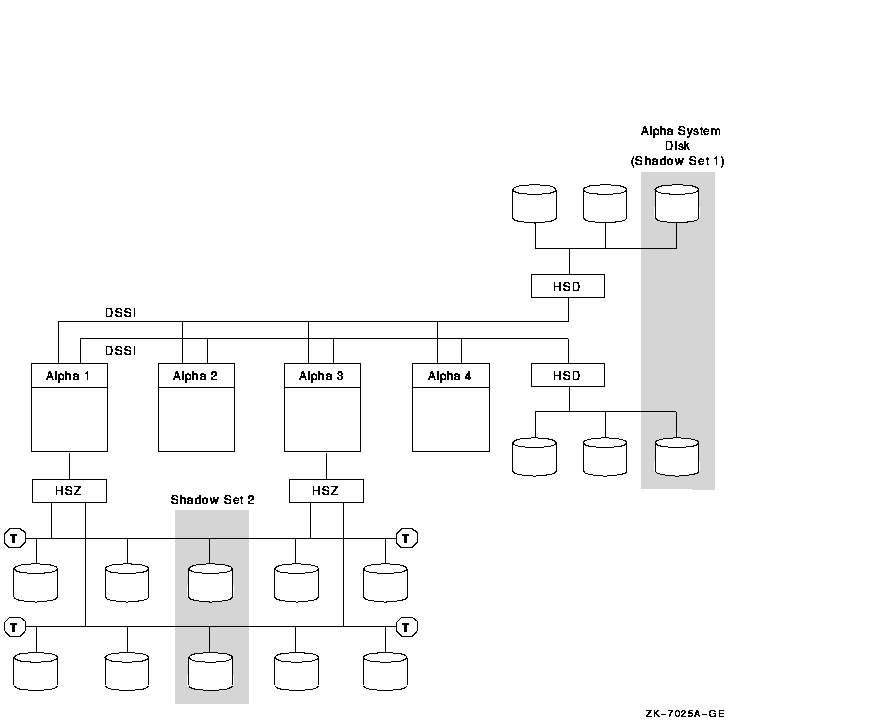
The advantages and disadvantages of the configuration shown in Figure 10-10 include:
Each MEMORY CHANNEL (MC) interconnect can have up to four nodes attached to each MEMORY CHANNEL hub. For two-hub configurations, each node must have two PCI adapters, and each adapter must be attached to a different hub. In a two-node configuration, no hub is required because one of the PCI adapters serves as a virtual hub.
Figure 10-11, Figure 10-12, and Figure 10-13 show a progression from a two-node MEMORY CHANNEL cluster to a four-node MEMORY CHANNEL cluster.
Reference: For additional configuration information
and a more detailed technical summary of how MEMORY CHANNEL works, see
Appendix B.
10.5.1 Two-Node MEMORY CHANNEL Cluster
In Figure 10-11, two nodes are connected by a MEMORY CHANNEL interconnect, a LAN (Ethernet, FDDI, or ATM) interconnect, and a SCSI interconnect.
Figure 10-11 Two-Node MEMORY CHANNEL OpenVMS Cluster
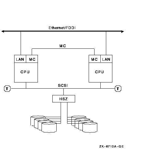
The advantages and disadvantages of the configuration shown in Figure 10-11 include:
If the OpenVMS Cluster in Figure 10-11 required more processing power
and better redundancy, this could lead to a configuration like the one
shown in Figure 10-12.
10.5.2 Three-Node MEMORY CHANNEL Cluster
In Figure 10-12, three nodes are connected by a high-speed MEMORY CHANNEL interconnect, as well as by a LAN (Ethernet, FDDI, or ATM) interconnect. These nodes also have shared, direct access to storage through the SCSI interconnect.
Figure 10-12 Three-Node MEMORY CHANNEL OpenVMS Cluster
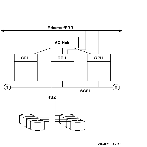
The advantages and disadvantages of the configuration shown in Figure 10-12 include:
If the configuration in Figure 10-12 required more storage, this could
lead to a configuration like the one shown in Figure 10-13.
10.5.3 Four-Node MEMORY CHANNEL OpenVMS Cluster
Figure 10-13, each node is connected by a MEMORY CHANNEL interconnect as well as by a CI interconnect.
Figure 10-13 MEMORY CHANNEL Cluster with a CI Cluster
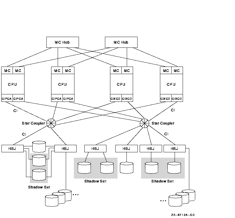
The advantages and disadvantages of the configuration shown in Figure 10-13 include:
SCSI-based OpenVMS Clusters allow commodity-priced storage devices to be used directly in OpenVMS Clusters. Using a SCSI interconnect in an OpenVMS Cluster offers you variations in distance, price, and performance capacity. This SCSI clustering capability is an ideal starting point when configuring a low-end, affordable cluster solution. SCSI clusters can range from desktop to deskside to departmental and larger configurations.
Note the following general limitations when using the SCSI interconnect:
The figures in this section show a progression from a two-node SCSI
configuration with modest storage to a four-node SCSI hub configuration
with maximum storage and further expansion capability.
10.6.1 Two-Node Fast-Wide SCSI Cluster
In Figure 10-14, two nodes are connected by a 25-m, fast-wide differential (FWD) SCSI bus, with MEMORY CHANNEL (or any) interconnect for internode traffic. The BA356 storage cabinet contains a power supply, a DWZZB single-ended to differential converter, and six disk drives. This configuration can have either narrow or wide disks.
Figure 10-14 Two-Node Fast-Wide SCSI Cluster
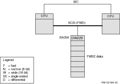
The advantages and disadvantages of the configuration shown in Figure 10-14 include:
If the configuration in Figure 10-14 required even more storage, this
could lead to a configuration like the one shown in Figure 10-15.
10.6.2 Two-Node Fast-Wide SCSI Cluster with HSZ Storage
In Figure 10-15, two nodes are connected by a 25-m, fast-wide differential (FWD) SCSI bus, with MEMORY CHANNEL (or any) interconnect for internode traffic. Multiple storage shelves are within the HSZ controller.
Figure 10-15 Two-Node Fast-Wide SCSI Cluster with HSZ Storage
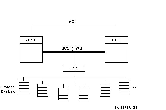
The advantages and disadvantages of the configuration shown in Figure 10-15 include:
In Figure 10-16, three nodes are connected by two 25-m, fast-wide (FWD) SCSI interconnects. Multiple storage shelves are contained in each HSZ controller, and more storage is contained in the BA356 at the top of the figure.
Figure 10-16 Three-Node Fast-Wide SCSI Cluster
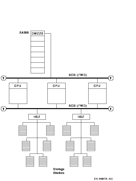
The advantages and disadvantages of the configuration shown in Figure 10-16 include:
Figure 10-17 shows four nodes connected by a SCSI hub. The SCSI hub obtains power and cooling from the storage cabinet, such as the BA356. The SCSI hub does not connect to the SCSI bus of the storage cabinet.
Figure 10-17 Four-Node Ultra SCSI Hub Configuration
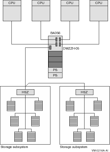
The advantages and disadvantages of the configuration shown in Figure 10-17 include:
The number of satellites in an OpenVMS Cluster and the amount of storage that is MSCP served determine the need for the quantity and capacity of the servers. Satellites are systems that do not have direct access to a system disk and other OpenVMS Cluster storage. Satellites are usually workstations, but they can be any OpenVMS Cluster node that is served storage by other nodes in the OpenVMS Cluster.
Each Ethernet LAN segment should have only 10 to 20 satellite nodes
attached. Figure 10-18, Figure 10-19, Figure 10-20, and
Figure 10-21 show a progression from a 6-satellite LAN to a
45-satellite LAN.
10.7.1 Six-Satellite OpenVMS Cluster
In Figure 10-18, six satellites and a boot server are connected by Ethernet.
Figure 10-18 Six-Satellite LAN OpenVMS Cluster
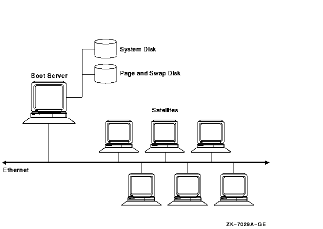
The advantages and disadvantages of the configuration shown in Figure 10-18 include:
If the boot server in Figure 10-18 became a bottleneck, a configuration like the one shown in Figure 10-19 would be required.
| Previous | Next | Contents | Index |
![[Go to the documentation home page]](../../images/buttons/bn_site_home.gif)
![[How to order documentation]](../../images/buttons/bn_order_docs.gif)
![[Help on this site]](../../images/buttons/bn_site_help.gif)
![[How to contact us]](../../images/buttons/bn_comments.gif)
|
| privacy and legal statement | ||
| 6318PRO_014.HTML | ||