![[Compaq]](../../images/compaq.gif)
![[Go to the documentation home page]](../../images/buttons/bn_site_home.gif)
![[How to order documentation]](../../images/buttons/bn_order_docs.gif)
![[Help on this site]](../../images/buttons/bn_site_help.gif)
![[How to contact us]](../../images/buttons/bn_comments.gif)
![[OpenVMS documentation]](../../images/ovmsdoc_sec_head.gif)
| Document revision date: 19 July 1999 | |
![[Compaq]](../../images/compaq.gif) |
![[Go to the documentation home page]](../../images/buttons/bn_site_home.gif)
![[How to order documentation]](../../images/buttons/bn_order_docs.gif)
![[Help on this site]](../../images/buttons/bn_site_help.gif)
![[How to contact us]](../../images/buttons/bn_comments.gif)
|
![[OpenVMS documentation]](../../images/ovmsdoc_sec_head.gif)
|
|
| Previous | Contents | Index |
Figure 10-19 shows six satellites and two boot servers connected by Ethernet. Boot server 1 and boot server 2 perform MSCP server dynamic load balancing: they arbitrate and share the work load between them and if one node stops functioning, the other takes over. MSCP dynamic load balancing requires shared access to storage.
Figure 10-19 Six-Satellite LAN OpenVMS Cluster with Two Boot Nodes
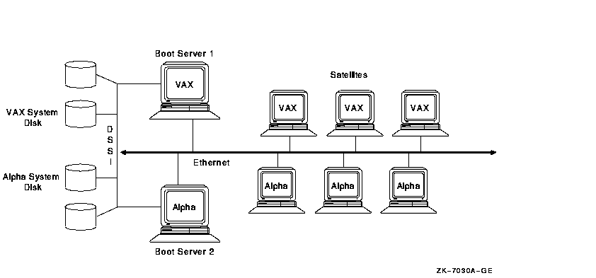
The advantages and disadvantages of the configuration shown in Figure 10-19 include:
If the LAN in Figure 10-19 became an OpenVMS Cluster bottleneck, this
could lead to a configuration like the one shown in Figure 10-20.
10.7.3 Twelve-Satellite LAN OpenVMS Cluster with Two LAN Segments
Figure 10-20 shows 12 satellites and 2 boot servers connected by two Ethernet segments. These two Ethernet segments are also joined by a LAN bridge. Because each satellite has dual paths to storage, this configuration also features MSCP dynamic load balancing.
Figure 10-20 Twelve-Satellite OpenVMS Cluster with Two LAN Segments
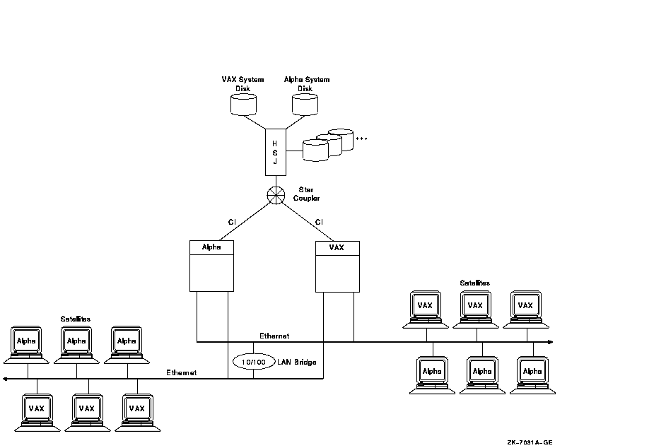
The advantages and disadvantages of the configuration shown in Figure 10-20 include:
If the OpenVMS Cluster in Figure 10-20 needed to grow beyond its
current limits, this could lead to a configuration like the one shown
in Figure 10-21.
10.7.4 Forty-Five Satellite OpenVMS Cluster with FDDI Ring
Figure 10-21 shows a large, 51-node OpenVMS Cluster that includes 45 satellite nodes. The three boot servers, Alpha 1, Alpha 2, and Alpha 3, share three disks: a common disk, a page and swap disk, and a system disk. The FDDI ring has three LAN segments attached. Each segment has 15 workstation satellites as well as its own boot node.
Figure 10-21 Forty-Five Satellite OpenVMS Cluster with FDDI Ring
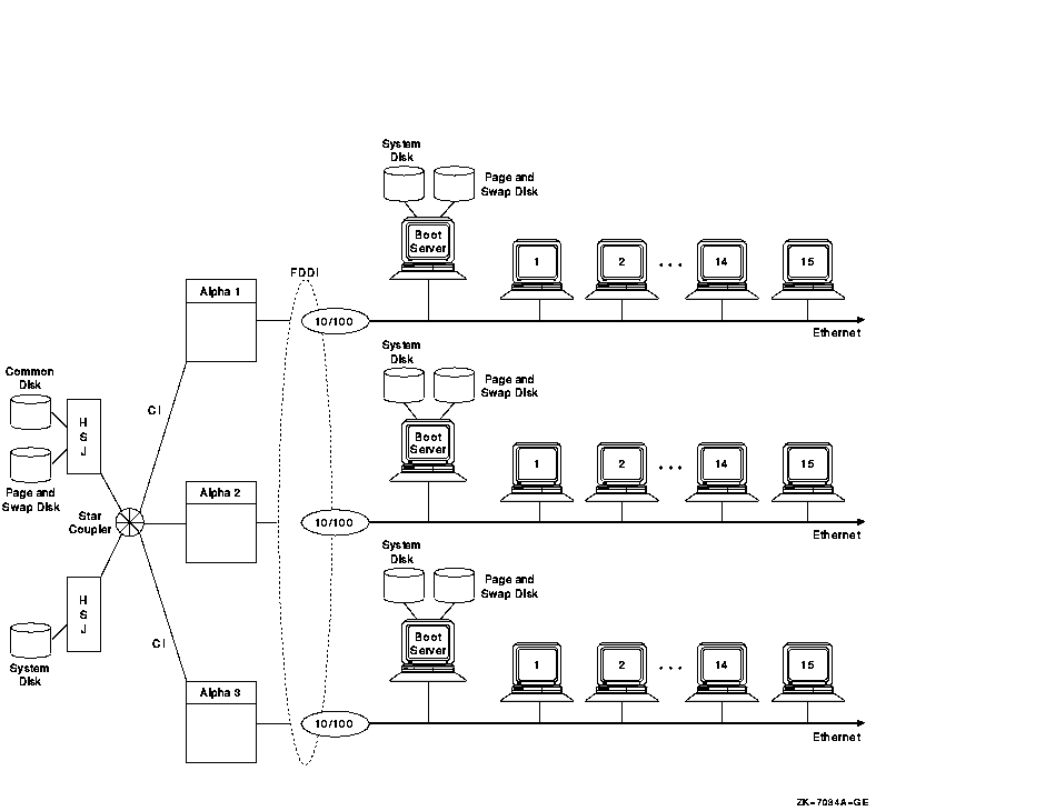
The advantages and disadvantages of the configuration shown in Figure 10-21 include:
Figure 10-22 shows an OpenVMS Cluster configuration that provides high performance and high availability on the FDDI ring.
Figure 10-22 High-Powered Workstation Server Configuration
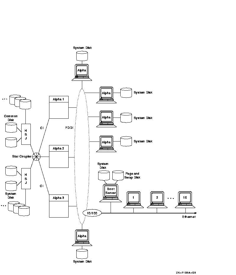
In Figure 10-22, several Alpha workstations, each with its own system
disk, are connected to the FDDI ring. Putting Alpha workstations on the
FDDI provides high performance because each workstation has direct
access to its system disk. In addition, the FDDI bandwidth is higher
than that of the Ethernet. Because Alpha workstations have FDDI
adapters, putting these workstations on an FDDI is a useful alternative
for critical workstation requirements. FDDI is 10 times faster than
Ethernet, and Alpha workstations have processing capacity that can take
advantage of FDDI's speed.
10.7.6 Guidelines for OpenVMS Clusters with Satellites
The following are guidelines for setting up an OpenVMS Cluster with satellites:
You can use bridges between LAN segments to form an extended LAN (ELAN). This can increase availability, distance, and aggregate bandwidth as compared with a single LAN. However, an ELAN can increase delay and can reduce bandwidth on some paths. Factors such as packet loss, queuing delays, and packet size can also affect ELAN performance. Table 10-3 provides guidelines for ensuring adequate LAN performance when dealing with such factors.
| Factor | Guidelines |
|---|---|
| Propagation delay |
The amount of time it takes a packet to traverse the ELAN depends on
the distance it travels and the number of times it is relayed from one
link to another by a bridge or a station on the FDDI ring. If
responsiveness is critical, then you must control these factors.
When an FDDI is used for OpenVMS Cluster communications, the ring latency when the FDDI ring is idle should not exceed 400 ms. FDDI packets travel at 5.085 microseconds/km and each station causes an approximate 1-ms delay between receiving and transmitting. You can calculate FDDI latency by using the following algorithm: Latency = (distance in km) * (5.085 ms/km) + (number of stations) * (1 ms/station) For high-performance applications, limit the number of bridges between nodes to two. For situations in which high performance is not required, you can use up to seven bridges between nodes. |
| Queuing delay |
Queuing occurs when the instantaneous arrival rate at bridges and host
adapters exceeds the service rate. You can control queuing by:
|
| Packet loss |
Packets that are not delivered by the ELAN require retransmission,
which wastes network resources, increases delay, and reduces bandwidth.
Bridges and adapters discard packets when they become congested. You
can reduce packet loss by controlling queuing, as previously described.
Packets are also discarded when they become damaged in transit. You can control this problem by observing LAN hardware configuration rules, removing sources of electrical interference, and ensuring that all hardware is operating correctly. Packet loss can also be reduced by using VMS Version 5.5--2 or later, which has PEDRIVER congestion control. The retransmission timeout rate, which is a symptom of packet loss, must be less than 1 timeout in 1000 transmissions for OpenVMS Cluster traffic from one node to another. ELAN paths that are used for high-performance applications should have a significantly lower rate. Monitor the occurrence of retransmission timeouts in the OpenVMS Cluster. Reference: For information about monitoring the occurrence of retransmission timeouts, see OpenVMS Cluster Systems. |
| Bridge recovery delay |
Choose bridges with fast self-test time and adjust bridges for fast
automatic reconfiguration.
Reference: Refer to OpenVMS Cluster Systems for more information about LAN bridge failover. |
| Bandwidth |
All LAN paths used for OpenVMS Cluster communication must operate with
a nominal bandwidth of at least 10 Mb/s. The average LAN segment
utilization should not exceed 60% for any 10-second interval.
Use FDDI exclusively on the communication paths that have the highest performance requirements. Do not put an Ethernet LAN segment between two FDDI segments. FDDI bandwidth is significantly greater, and the Ethernet LAN will become a bottleneck. This strategy is especially ineffective if a server on one FDDI must serve clients on another FDDI with an Ethernet LAN between them. A more appropriate strategy is to put a server on an FDDI and put clients on an Ethernet LAN, as Figure 10-21 shows. |
| Traffic isolation |
Use bridges to isolate and localize the traffic between nodes that
communicate with each other frequently. For example, use bridges to
separate the OpenVMS Cluster from the rest of the ELAN and to separate
nodes within an OpenVMS Cluster that communicate frequently from the
rest of the OpenVMS Cluster.
Provide independent paths through the ELAN between critical systems that have multiple adapters. |
| Packet size |
You can adjust the NISCS_MAX_PKTSZ system parameter to use the full
FDDI packet size. Ensure that the ELAN path supports a data field of at
least 4474 bytes end to end.
Some failures cause traffic to switch from an ELAN path that supports 4474-byte packets to a path that supports only smaller packets. It is possible to implement automatic detection and recovery from these kinds of failures. This capability requires that the ELAN set the value of the priority field in the FDDI frame-control byte to zero when the packet is delivered on the destination FDDI link. Ethernet-to-FDDI bridges that conform to the IEEE 802.1 bridge specification provide this capability. |
In an OpenVMS Cluster with satellites and servers, specific system parameters can help you manage your OpenVMS Cluster more efficiently. Table 10-4 gives suggested values for these system parameters.
| System Parameter | Value for Satellites |
Value for Servers |
|---|---|---|
| LOCKDIRWT | 0 | 1--4 |
| SHADOW_MAX_COPY | 0 | 1--4 |
| MSCP_LOAD | 0 | 1 or 2 |
| NPAGEDYN | Higher than for standalone node | Higher than for satellite node |
| PAGEDYN | Higher than for standalone node | Higher than for satellite node |
| VOTES | 0 | 1 |
| EXPECTED_VOTES | Sum of OpenVMS Cluster votes | Sum of OpenVMS Cluster votes |
| RECNXINTERVL 1 | Equal on all nodes | Equal on all nodes |
Reference: For a more in-depth description of these
parameters, see OpenVMS Cluster Systems.
10.8 Scaling for I/Os
The ability to scale I/Os is an important factor in the growth of your OpenVMS Cluster. Adding more components to your OpenVMS Cluster requires high I/O throughput so that additional components do not create bottlenecks and decrease the performance of the entire OpenVMS Cluster. Many factors can affect I/O throughput:
These factors can affect I/O scalability either singly or in combination. The following sections explain these factors and suggest ways to maximize I/O throughput and scalability without having to change in your application.
Additional factors that affect I/O throughput are types of interconnects and types of storage subsystems.
Reference: See Chapter 4 for more information
about interconnects and Chapter 5 for more information about types
of storage subsystems.
10.8.1 MSCP Served Access to Storage
MSCP server capability provides a major benefit to OpenVMS Clusters: it enables communication between nodes and storage that are not directly connected to each other. However, MSCP served I/O does incur overhead. Figure 10-23 is a simplification of how packets require extra handling by the serving system.
Figure 10-23 Comparison of Direct and MSCP Served Access
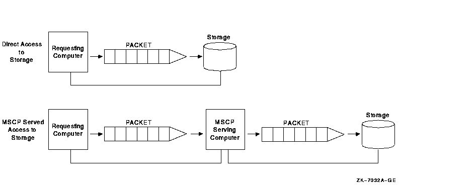
In Figure 10-23, an MSCP served packet requires an extra "stop" at another system before reaching its destination. When the MSCP served packet reaches the system associated with the target storage, the packet is handled as if for direct access.
In an OpenVMS Cluster that requires a large amount of MSCP serving, I/O
performance is not as efficient and scalability is decreased. The total
I/O throughput is approximately 20% less when I/O is MSCP served than
when it has direct access. Design your configuration so that a few
large nodes are serving many satellites rather than satellites serving
their local storage to the entire OpenVMS Cluster.
10.8.2 Disk Technologies
In recent years, the ability of CPUs to process information has far outstripped the ability of I/O subsystems to feed processors with data. The result is an increasing percentage of processor time spent waiting for I/O operations to complete.
Solid-state disks (SSDs), DECram, and RAID level 0 bridge this gap between processing speed and magnetic-disk access speed. Performance of magnetic disks is limited by seek and rotational latencies, while SSDs and DECram use memory, which provides nearly instant access.
RAID level 0 is the technique of spreading (or "striping") a single file across several disk volumes. The objective is to reduce or eliminate a bottleneck at a single disk by partitioning heavily accessed files into stripe sets and storing them on multiple devices. This technique increases parallelism across many disks for a single I/O.
Table 10-5 summarizes disk technologies and their features.
| Disk Technology | Characteristics |
|---|---|
| Magnetic disk |
Slowest access time.
Inexpensive. Available on multiple interconnects. |
| Solid-state disk |
Fastest access of any I/O subsystem device.
Highest throughput for write-intensive files. Available on multiple interconnects. |
| DECram |
Highest throughput for small to medium I/O requests.
Volatile storage; appropriate for temporary read-only files. Available on any Alpha or VAX system. |
| RAID level 0 | Available on HSJ and HSD controllers. |
Note: Shared, direct access to a solid-state disk or
to DECram is the fastest alternative for scaling I/Os.
10.8.3 Read/Write Ratio
The read/write ratio of your applications is a key factor in scaling I/O to shadow sets. MSCP writes to a shadow set are duplicated on the interconnect.
Therefore, an application that has 100% (100/0) read activity may benefit from volume shadowing because shadowing causes multiple paths to be used for the I/O activity. An application with a 50/50 ratio will cause more interconnect utilization because write activity requires that an I/O be sent to each shadow member. Delays may be caused by the time required to complete the slowest I/O.
To determine I/O read/write ratios, use the DCL command MONITOR IO.
10.8.4 I/O Size
Each I/O packet incurs processor and memory overhead, so grouping I/Os
together in one packet decreases overhead for all I/O activity. You can
achieve higher throughput if your application is designed to use bigger
packets. Smaller packets incur greater overhead.
10.8.5 Caches
Caching is the technique of storing recently or frequently used data in an area where it can be accessed more easily---in memory, in a controller, or in a disk. Caching complements solid-state disks, DECram, and RAID. Applications automatically benefit from the advantages of caching without any special coding. Caching reduces current and potential I/O bottlenecks within OpenVMS Cluster systems by reducing the number of I/Os between components.
Table 10-6 describes the three types of caching.
| Caching Type | Description |
|---|---|
| Host based | Cache that is resident in the host system's memory and services I/Os from the host. |
| Controller based | Cache that is resident in the storage controller and services data for all hosts. |
| Disk | Cache that is resident in a disk. |
Host-based disk caching provides different benefits from
controller-based and disk-based caching. In host-based disk caching,
the cache itself is not shareable among nodes. Controller-based and
disk-based caching are shareable because they are located in the
controller or disk, either of which is shareable.
10.8.6 Managing "Hot" Files
A "hot" file is a file in your system on which the most activity occurs. Hot files exist because, in many environments, approximately 80% of all I/O goes to 20% of data. This means that, of equal regions on a disk drive, 80% of the data being transferred goes to one place on a disk, as shown in Figure 10-24.
Figure 10-24 Hot-File Distribution
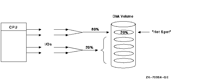
To increase the scalability of I/Os, focus on hot files, which can become a bottleneck if you do not manage them well. The activity in this area is expressed in I/Os, megabytes transferred, and queue depth.
RAID level 0 balances hot-file activity by spreading a single file over multiple disks. This reduces the performance impact of hot files.
Use the following DCL commands to analyze hot-file activity:
The MONITOR IO and the MONITOR MSCP commands enable you to find out which disk and which server are hot.
| Previous | Next | Contents | Index |
![[Go to the documentation home page]](../../images/buttons/bn_site_home.gif)
![[How to order documentation]](../../images/buttons/bn_order_docs.gif)
![[Help on this site]](../../images/buttons/bn_site_help.gif)
![[How to contact us]](../../images/buttons/bn_comments.gif)
|
| privacy and legal statement | ||
| 6318PRO_015.HTML | ||