DECdocument
Graphics Editor User's Guide
for Motif
Chapter 2
Creating Graphics
This chapter explains how to:
- Create objects (Section 2.1)
- Use the mouse buttons and keys to create objects (Section 2.2)
- Use creation points (Section 2.3)
- Delete objects (Section 2.4)
- Create a polygon (Section 2.5)
- Use the horizontal and vertical constraint settings (Section 2.6)
- Enter text (Section 2.7)
- Clear the screen (Section 2.8)
- Create a graphic (Section 2.9)
2.1 Creating an Object
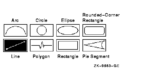
The Graphics Editor provides eight object icons on the Control Panel to
create graphics. By combining these objects with one another, you can
create a variety of graphics. Figure 2-1 shows the object icons.
Figure 2-1 Oject Icons
You create most objects with a similar sequence of steps. The following
exercises describe these steps.
The Drawing window must have focus for any keystrokes from the keyboard
to work, such as Ctrl/x, arrow keys, or the Return key. If the Drawing
window does not have focus, click MB1 anywhere in the Drawing window;
the title bar is highlighted.
To create a circle:
- Choose the Circle icon on the Control Panel (click MB1 on the
Circle icon or press Ctrl/2).
- Move the pointer to the Drawing window where you want the center of
the circle. Click MB2 to fix the center point.
- Move the pointer out from the center to set the radius. Click MB2
to finish the circle which should appear as shown here:

To create an arc:
- Choose the Arc icon.
- Move the pointer to the Drawing window where you want one end point
of the arc. Click MB2.
- Move the pointer to the right and click MB2 to set the second end
point.
- Move the pointer to set the curve of the arc. Click MB2 to finish
the arc, which should appear as shown here:

To create another arc and cancel its creation before completing it:
- Move the pointer to the Drawing window and click MB2.
- Move the pointer to the right and click MB2 again.
- Click MB3. The arc is deleted and the creation process is stopped.
To create a square around the circle and use the arrow keys to position
the square:
- Choose the Rectangle icon.
- Move the pointer outside the circle you created and click MB2.
- Move the pointer to draw a square around the circle, but do not
click MB2.
- Press the down arrow key. The square you are drawing moves down
slightly. Continue to press the arrow keys to position the two sides of
the square opposite the pointer close to the circle perimeter.
- Move the pointer to position the remaining two sides.
- Click MB2 or press Return to finish the square which should appear
as shown here:

2.2 Summary of Mouse Buttons and Keys Used for Creating Objects
Table 2-1 summarizes the mouse buttons and keys you use for creating
objects.
Table 2-1 Mouse Buttons and Keys Used for Creation
| Use |
To |
|
MB1 or a Ctrl key sequence¹
|
Select an object icon.
|
|
MB2 or Return
|
Create the object (specify key points on the object, such as end
points) and finish the object creation. Use Return for positioning when
slight movements of the object must be avoided.
|
|
MB3
|
Cancel the creation process and delete the object.
|
|
Delete or Backspace key
|
Deletes an existing object or a group of objects.
|
|
Remove key
|
Deletes one or more selected objects at a time.
|
|
Insert
|
Replaces one or more selected objects deleted by the Remove key.
|
|
Select
|
Reselects the last created object. Only reselects one object.
|
|
Arrow keys
|
Move the object one pixel at a time in the direction of the arrow
during creation.
|
|
Shift key
|
Constrains an object. For example, by using the Shift key you can
create an ellipse from a circle.
|
¹See Appendix B for control key sequences.
These are general functions for creating objects. See the Hints window
or the context-sensitive help for information on the use of each mouse
button while using the Graphics Editor.
2.3 Creation Points
When you create the circle and arc, you specify two points for the
circle (center and radius) and three points for the arc (two end points
and a point on the arc). These points are called creation
points.
Each object has two or more creation points. It is important to know
where an object's creation points are because you must click MB2 on
each creation point to set it.
When you select an icon, the creation points for the object are
indicated by dots on the object icon.
The Polygon icon does not show creation points because this object can
contain a variable number of points. See Section 2.5 for more
information on creating polygons.
2.4 Deleting an Object
To delete an object you have drawn:
- Choose Delete from the Control Panel.
- Move the pointer to any point on the arc and click MB1. An extent
rectangle surrounds the arc indicating the object is selected as shown
here:

If the extent rectangle does not suround the arc, click MB1. Then
move the pointer and click MB1 to try again to select the arc.
- Click MB2 to delete the arc.
Chapter 3 contains more information on deleting objects and text.
2.5 Creating a Polygon
The Polygon icon has two object shapes: polyline and polyarc. To
display the polyline and polyarc icons, choose the Line icon followed
by the Arc icon. Note that the Polygon icon changes as the line and arc
icons are selected.
The polyline lets you connect line segments, and the polyarc lets you
connect arcs. You can use both polygon types to create open or closed
polygons.
Creating Polygons
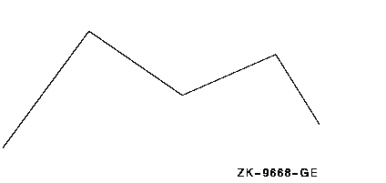
To create an open polyline:
- Choose the Line icon then choose the Polygon icon.
- Move the pointer to the Drawing window and click MB2.
- Draw a line and click MB2.
- Draw a few more lines at different angles and click MB2 after each
line.
- Click MB1 to finish the polyline. The results shown here:
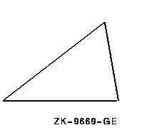
To create a closed polyline:
- Choose the Line icon and move the pointer to the Drawing window and
click MB2.
- Draw a line and click MB2.
- Draw another line but do not click MB2. Without moving the pointer,
double click MB1. The polyline is closed, creating a triangle as shown
here:
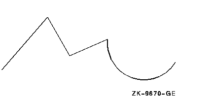
To create a polygon consisting of a polyline and polyarc:
- Draw a polyline with at least three lines.
- Click MB3 to pause the creation. The pointer changes to a mouse
shape indicating that you are still working on a polygon.
- Choose the Arc icon.
- Draw at least one arc, clicking MB2 to set each arc point. You can
connect the polyarc to the polyline or separate them. To connect the
segments, position the dot in the center of the mouse cursor on the end
point of the polyline. Refer to the following figure:
- Click MB3. The last arc segment is deleted.
- Click MB3. Another arc or line segment is deleted. Segments are
deleted in reverse order.
- Do one of the following tasks:
- Continue to click MB3 to delete all segments
- Start drawing another polyline or polyarc
- Click MB1 to finish the polygon creation
2.5.1 Summary of Polygon Creation
Table 2-2 summarizes your options once you start creating a polygon.
When you finish a polygon, all segments are joined together as a single
object.
Table 2-2 Creating Polygons
| If you want to... |
Do this... |
|
Continue creating more line or arc segments
|
Click MB2 on the creation points
|
|
Complete the current segment and finish the polygon
|
Click MB1
|
|
Complete the current segment to finish and automatically close the
polygon with a straight line segment drawn between the first and last
polygon points
|
Double click MB1
|
|
Delete the current segment and pause
|
Click MB3¹
|
|
Delete the current segment and finish the polygon
|
Click MB3, then MB1
|
|
Delete segments one at a time until the last segment is deleted
|
Repeatedly click MB3
|
|
Draw freehand
|
Press and hold MB2 and move the mouse
|
|
Erase freehand drawing
|
Press and hold MB3 and roll the mouse back over the freehand drawing
|
¹If you pause the creation, you can: - Move the pointer to
a different position to create an unconnected polygon.
- Select a
different polygon type and continue drawing.
- Adjust the editor, for
example, turn on a drawing grid or turn on gravity. See the
context-sensitive help for information on a grid and gravity.
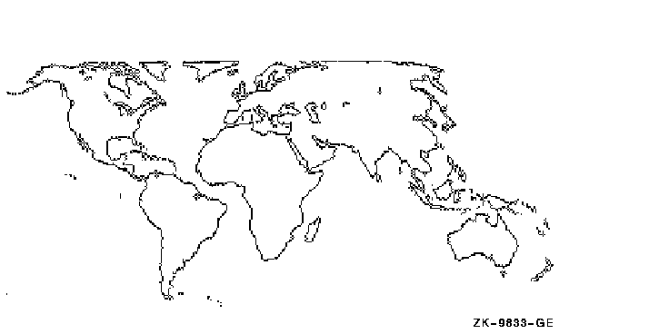
Figure 2-2 shows a very complex drawing that was done using polyline
and polyarc segments. It shows the potential of this object icon for
advanced graphics designers.
Figure 2-2 Drawing Created Using Polygon Icon
2.6 Using Horizontal and Vertical Constraints
The horizontal and vertical constraints place limitations on what
happens when you create or edit objects. For example, you can use the
constraints during creation to create straight lines and perfect
squares, or during editing to move objects horizontally, vertically, or
at a 45-degree angle.
You set constraints in two ways:
- Use the horizontal or vertical constraints on the Control Panel
- Use the Shift key
To draw a line with the Horizontal constraint indicator set:
- Turn on the Horizontal constraint indicator on the Control Panel.
- Choose the Line icon and begin drawing a line. Note that you can
only draw the line horizontally to the right or left of your starting
point.
- Press Shift to move the pointer in a circle around the starting
point. Note that the constraint is temporarily removed.
- Click MB2 to finish the line.
- Turn off the Horizontal constraint indicator.
To draw another line using the Shift key constraint:
- Begin drawing another line.
- Press Shift.
- Move the pointer horizontally, then in a circle around the starting
point. Note that the line is constrained horizontally, vertically, or
45-degrees from any horizontal and vertical line.
- Click MB2 to finish the line.
To draw a rectangle with and without constraints set:
- Choose the Rectangle icon.
- Begin drawing a rectangle.
- Press Shift. The rectangle is now restricted to a square.
- Click MB2 to finish the square.
2.6.1 Summary of Horizontal and Vertical Constraints
There are two ways to set constraints:
- Use the Horizontal and Vertical constraints on the Control Panel
These constraints affect object creation or editing as long as they
are set. To set these constraints, turn on one or both constraint
indicators before starting the creation or editing operation. If both
constraints are set, objects can also be constrained to a 45-degree
angle.
- Use the Shift key
The Shift key sets a temporary constraint
(horizontal, vertical, and 45 degree angle) that remains in effect
until the object creation or editing is completed or until you press
the Shift key again to remove the constraint. To set this constraint,
press the Shift key during the creation or editing operation.
If you are creating an object, constraints may or may not affect the
object creation. The following table shows the effect of setting
constraints (with the Shift key or the constraint indicators):
| Object |
Constraint Limitation |
|
Arc
|
No effect
|
|
Circle
|
No effect
|
|
Ellipse
|
Circle
|
|
Line
|
Line (horizontal, vertical, or at a 45-degree angle) as specified by
the constraint
|
|
Pie segment
|
Pie segment with equal line segments
|
|
Polyarc
|
No effect
|
|
Polyline
|
Line (horizontal, vertical, or at a 45-degree angle) as specified by
the constraint
|
|
Rectangle
|
Square
|
|
Rounded-corner rectangle
|
Rounded-corner square
|
2.7 Entering Text
The text defaults are:
- 12-point Courier font (current font is displayed at the top of the
Control Panel)
- Left-justification
- Insertion text mode
For information on changing text fonts, text justification, or text
mode, see Chapter 3.
To enter text in the drawing area:
- Click MB1 anywhere on the Drawing window to give it keyboard focus.
- Position the pointer where you want the text to begin and type the
word GRAPHICS.
- Press Return.
- Type EDITOR. Note that the two words are left-justified.
- Click MB3. The word EDITOR is deleted.
- Type CREATION.
- Hold down the Ctrl key and press the left arrow key several times.
Move the word CREATION to align it under GRAPHICS. Use other Ctrl/arrow
keys if necessary.
- Click MB2 to finish the text.
2.7.1 Summary of Text Entry
Use the following guidelines to enter text:
| To... |
Do the following... |
|
Enter text
|
Position the pointer where you want the text to begin and type the
text. A text insertion cursor appears just to the right of the last
letter typed.
|
|
Enter a second line of text
|
Press Return and continue typing. The second line is left-aligned with
the first line.
|
|
Finish entering text and retain it
|
Click MB2.
|
|
Cancel the current line of text you are entering
|
Click MB3.
|
Use the following keys when entering or editing text:
| Key |
Function |
|
Left and right arrow keys
|
Move the text insertion cursor within the text.
|
|
Delete key
|
Delete a character.
|
|
Ctrl/A
|
Toggle between insert and overstrike text mode.
|
|
Ctrl/E
|
Move the text insertion cursor to the end of the line.
|
|
Ctrl/H
|
Move the text insertion cursor to the beginning of the line.
|
|
Ctrl/K
|
Delete from the text insertion cursor position to the end of the line.
|
|
Ctrl/Y
|
Undelete the characters deleted with Ctrl/K and insert them at the text
insertion cursor.
|
|
Ctrl/arrow keys
|
Move the text one pixel at a time in the direction of the arrow.
|
2.8 Clearing the Screen
Before starting the following exercises, clear the screen:
- Choose Delete All from the Edit menu on the Drawing window.
The
Confirm Delete All dialog box appears in Figure 2-3.
Figure 2-3 Delete All Dialog Box
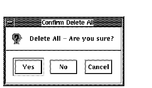
- Choose Yes. All objects on the screen are deleted.
2.9 Creating a Graphic
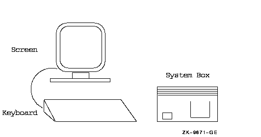
The next five exercises show you how to use the Graphics Editor to create
the following graphic drawing. In Chapter 3, you will use this graphic
to learn how to edit graphics.
2.9.1 Draw the Screen and Stand
To draw the following screen and stand:
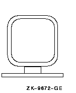
- Choose the Rounded-Corner Rectangle icon.
- Position the pointer in the Drawing window where you want to draw
the screen and click MB2.
- Move the pointer to the opposite corner to create the desired
screen size.
- Click MB2 to confirm.
- Repeat steps 2 and 3 to draw a second screen inside the first
screen. You can use the arrow keys to position the second screen before
completing it.
- Choose the Rectangle icon.
- Draw two different-sized rectangles under the screen to indicate
the workstation stand. Use arrow keys if necessary for positioning.
2.9.2 Draw the Keyboard
You can draw the keyboard in several ways. This exercise shows how to
use the Polygon icon to draw the keyboard. The numbers on the following
keyboard graphic match the step numbers in the procedure. Use the
numbers as an aid in drawing the keyboard lines in the correct sequence.
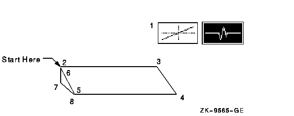
- Choose the Line icon and then choose the Polygon icon.
- Position the pointer where you want the upper left corner of the
keyboard and click MB2.
- Press Shift to set the Horizontal constraint. Draw a horizontal
line to indicate the top of the keyboard. Click MB2.
- Draw the right side of the keyboard at about a 45-degree angle.
Click MB2.
- Press Shift to reset the Horizontal constraint. Draw the bottom of
the keyboard. Click MB2.
- Draw the left side of the keyboard parallel to the right side.
Click MB2.
- Draw the short line at the left side of the keyboard to indicate
depth. Click MB2.
- Draw the final segment of the keyboard. Click MB1.
2.9.3 Draw the System Box
To draw the following system box:
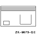
- Choose the Rectangle icon.
- Draw a rectangle for the system box. Click MB2 to start and finish
the rectangle.
- Draw a smaller rectangle in the lower left corner to indicate the
on/off switch.
- Choose the Line icon.
- Turn on the Horizontal constraint indicator.
- Draw four horizontal lines across the top of the system box. Click
MB2 to start and finish each line. Use arrow keys if necessary for
positioning before finishing each line.
- Turn on the Vertical constraint indicator. Both constraints are now
set.
- Choose the Polygon icon.
- Draw the box indicating the disk location. Click MB2 to set the
first three points.
- Click MB1 to set the last point and finish the polygon.
- Turn off the Horizontal and Vertical constraint indicators.
2.9.4 Draw the Cable
To draw the following cable attached to the screen:
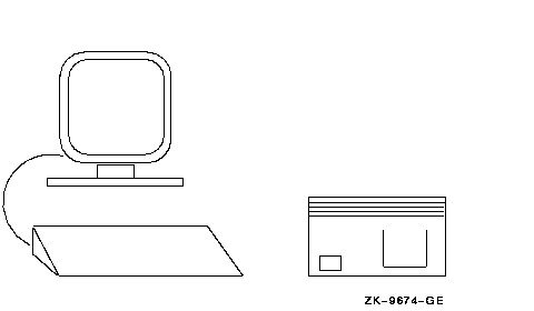
- Choose the Arc icon.
- Position the pointer at the left side of the keyboard and click MB2.
- Move the pointer to the lower left corner of the workstation and
click MB2.
- Move the pointer to push the arc to the desired shape. Click MB2 to
confirm.


