![[Compaq]](../../images/compaq.gif)
![[Go to the documentation home page]](../../images/buttons/bn_site_home.gif)
![[How to order documentation]](../../images/buttons/bn_order_docs.gif)
![[Help on this site]](../../images/buttons/bn_site_help.gif)
![[How to contact us]](../../images/buttons/bn_comments.gif)
![[OpenVMS documentation]](../../images/ovmsdoc_sec_head.gif)
| Document revision date: 30 March 2001 | |
![[Compaq]](../../images/compaq.gif) |
![[Go to the documentation home page]](../../images/buttons/bn_site_home.gif)
![[How to order documentation]](../../images/buttons/bn_order_docs.gif)
![[Help on this site]](../../images/buttons/bn_site_help.gif)
![[How to contact us]](../../images/buttons/bn_comments.gif)
|
![[OpenVMS documentation]](../../images/ovmsdoc_sec_head.gif)
|
|
| Previous | Contents | Index |
When you click the Cluster Summary tab on an OpenVMS Node Summary page, the Availability Manager displays the OpenVMS Cluster Summary page (Figure 3-18).
This page contains cluster interconnect information for an entire cluster as well as detailed information about each node in the cluster, including System Communications Services (SCS) connections and LAN virtual circuits for individual nodes. The data items shown on the page correspond to data that the Show Cluster utility (SHOW CLUSTER) displays for the SYSTEMS and MEMBERS classes.
Figure 3-18 OpenVMS Cluster Summary Page
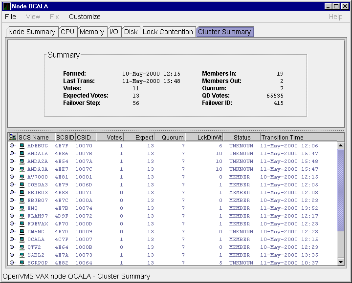
The two panes in the Cluster Summary page display the following information:
The following sections discuss these two panes.
Following are notes about the display of data in the panes:
LOVOTE, 'node' VOTES count is close to or below QUORUM
|
Table 3-5 describes the Summary pane data (see Figure 3-18).
| Data | Description |
|---|---|
| Formed | Date and time the cluster was formed. |
| Last Trans | Date and time of the most recent cluster state transition. |
| Votes | Total number of quorum votes being contributed by all cluster members and by the quorum disk. |
| Expected Votes | Number of votes expected to be contributed by all members of the cluster as determined by the connection manager. This value is based on the maximum EXPECTED_VOTES system parameter and the maximized value of the VOTES system parameter. |
| Failover Step | Current failover step index. Shows which step in the sequence of failover steps the failover is currently executing. |
| Members In | Number of cluster members to which the Availability Manager has a connection. |
| Members Out | Number of cluster members to which the Availability Manager either has no connection or has lost connection. |
| Quorum | Number of votes required to keep the cluster above quorum. |
| QD Votes | Number of votes given to the quorum disk. A value of 65535 means there is no quorum disk. |
| Failover ID | Failover instance identification. Unique ID of a failover sequence that indicates to system managers whether a failover has occurred since the last time they checked. |
The Cluster Members pane lists all the nodes in the cluster and provides detailed information about each one. The first level of information in the Cluster Members pane contains cluster member data (see Figure 3-18), which is described in Table 3-6.
| Data | Description |
|---|---|
| SCS Name | System Communications Services (SCS) name for the node (system parameter SCSNODE). |
| SCSID | SCS identification for the node (system parameter SCSYSTEMID). |
| CSID | Cluster system identification. |
| Votes | Number of votes the member contributes. |
| Expect | Member's expected votes as set by the EXPECTED_VOTES system parameter. |
| Quorum | Number of votes that must be present for the cluster to function and permit user activity. |
| LckDirWt | Lock manager distributed directory weight as determined by the LCKDIRWT system parameter. |
| Status | Current cluster member status: MEMBER, UNKNOWN, or BRK_NON (break nonmember). |
| Transition Time | Time cluster member had last transition. |
SCA VC data includes information about members' virtual circuits to other members of the cluster. More than one virtual circuit indicates more than one path to the other member.
The data displayed is similar to the information that the Show Cluster utility (SHOW CLUSTER) displays for the CIRCUITS, CONNECTIONS, and COUNTERS classes. However, in Availability Manager Version 1.3 and earlier, SHOW CLUSTER displays show connections and virtual circuits to other OpenVMS nodes only; they do not show connections and virtual circuits to the DIGITAL Storage Architecture (DSA) devices, such as FDDI or DSSI disk controllers. This limitation will be fixed in a future release of the Availability Manager software.
You can display virtual circuit data by double-clicking the SCS name of a node. Figure 3-19 is an example of virtual circuit data on a Cluster Summary page. (Because it is very wide, the illustration splits the screen into two sections; the bottom screen is a continuation of the top screen.)
Figure 3-19 Virtual Circuit Data Page
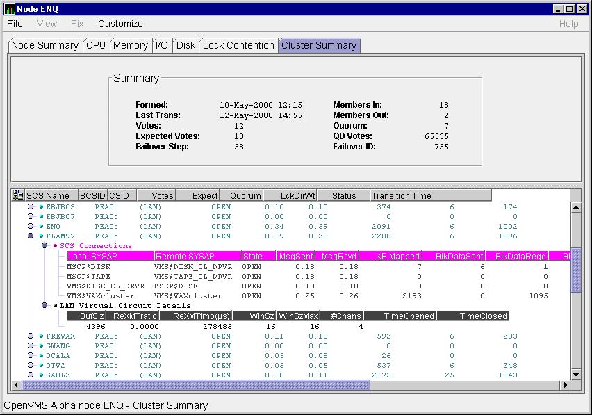
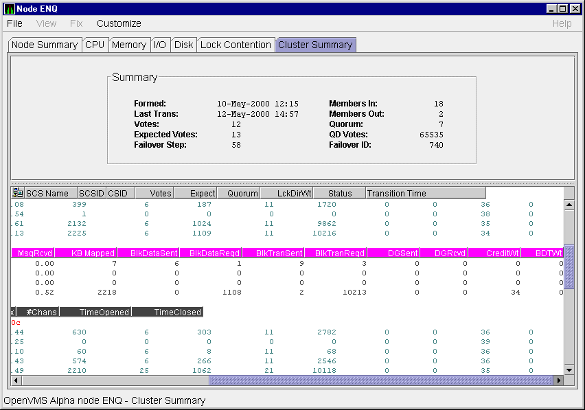
Table 3-7 describes virtual circuit data. Each line shows either a summary of all system applications (SYSAPs) that use virtual circuit communication or the communication on the connection between a local and a remote SYSAP.
| Data | Description |
|---|---|
| NodeName | SCS name of the remotely connected node. |
| LPortName | The device name of the local port associated with the circuit. |
| RPortType | The type of remote port associated with the circuit. |
| State | The state of the virtual circuit connection. |
| MsgSent | Rate that messages are sent on the virtual circuit. |
| MsgRcvd | Rate that messages are received on the virtual circuit. |
| KB Mapped | Number of kilobytes mapped for block data transfer using the virtual circuit. |
| BlkDataSent | Number of kilobytes sent on the virtual circuit by this node using send block data transfers. |
| BlkDataReqd | Number of kilobytes requested on the virtual circuit by this node using request block data transfers. |
| BlkTransSent | Number of send block data transfers by this node on the virtual circuit. |
| BlkTransReqd | Number of request block data transfers by this node on the virtual circuit. |
| DGSent | Number of datagrams sent by this node on the virtual circuit. |
| DGRcvd | Number of datagrams received from the remote system on the virtual circuit. |
| CreditWt | Number of times any connection on the virtual circuit had to wait for a send credit. |
| BDTWt | Number of times any connection on the virtual circuit had to wait for a buffer descriptor. |
You can display SCS connections data by double-clicking the SCS Connections icon displayed under a virtual circuit node name.
See Figure 3-19 for SCS connections data on a Cluster Summary page. Table 3-8 describes the SCS connections data.
| Data | Description |
|---|---|
| Local SYSAP | Name of the local system application using the SCS connection. |
| Remote SYSAP | Name of the remote system application communicated with using the SCS connection. |
| State | The state of the SCS connection. |
| MsgSent | Rate that messages are sent to the remote SYSAP using the SCS connection. |
| MsgRcvd | Rate that messages are received from the remote SYSAP using the SCS connection. |
| KB Mapped | Number of kilobytes mapped for block data transfer using the SCS connection. Note: This field is available only in raw data format. |
| BlkDataSent | Number of kilobytes sent on the SCS connection by this node using send block data transfers. |
| BlkDataReqd | Number of kilobytes the data requested on the SCS connection by this node using request block data transfers. |
| BlkTransSent | Number of send block data transfers by this node on the SCS connection. |
| BlkTransReqd | Number of request block data transfers by this node on the SCS connection. |
| DGSent | Number of datagrams sent by this node on the SCS connection. |
| DGRcvd | Number of datagrams received from the remote system on the SCS connection. |
| CreditWt | Number of times the connection had to wait for a send credit. |
| BDTWt | Number of times the connection had to wait for a buffer descriptor. |
You can display LAN virtual circuit details by double-clicking the icon preceding that heading on the Cluster Summary page. The data items displayed depend of the type of virtual circuit. Currently, this feature is available only for LAN virtual circuits.
See Figure 3-19 for a LAN virtual circuit data display. Table 3-9 describes the LAN virtual circuit details data.
| Data | Description |
|---|---|
| BufSz | Maximum data buffer size in use by this LAN virtual circuit. |
| ReXMTRatio | Ratio of retransmitted to transmitted packets during the most recent data collection interval. |
| ReXMTTimOut (µs) | Retransmission timeout (in microseconds). The amount of time the virtual circuit will wait for acknowledgment of a packet's receipt before retransmitting the packet. |
| WinSz | Current value of the transmit window (or pipe quota). Maximum number of packets that will be sent before stopping to await an acknowledgment. After a timeout, the transmit window is reset to 1 to decrease congestion and is allowed to increase as acknowledgments are received. |
| WinSzMax | Maximum transmit window size currently allowed for the virtual circuit. |
| #Chans | Number of channels 1 available to the virtual circuit. |
| TimeOpened | Most recent time the virtual circuit was opened. Not implemented in this release. |
| TimeClosed | Most recent time the virtual circuit was closed. Not implemented in this release. |
For more detailed explanations of these data, refer to the NISCA
troubleshooting information in the OpenVMS Cluster Systems manual.
3.2.8 OpenVMS Network Interconnect for the System Communication Architecture (NISCA) Pages
The Network Interconnect for the System Communication Architecture (NISCA) is the transport protocol responsible for carrying messages such as disk I/Os and lock messages across Ethernet and FDDI LANs to other nodes in the cluster. More detailed information about the protocol is in the OpenVMS Cluster Systems manual.
The NISCA pages show detailed information about the LAN (Ethernet or FDDI) connection between two nodes. The Availability Manager displays one window for each LAN virtual circuit.
The pages are intended primarily as real-time aids to diagnosing LAN-related problems. The OpenVMS Cluster Systems manual describes the parameters shown in these pages and tells how to diagnose LAN-related cluster problems. The pages provide the same information as the OpenVMS System Dump Analyzer (SDA) command SHOW PORTS/VC=VC_node-name. (VC refers to a virtual circuit; node-name refers to a node in the cluster. The system defines VC-node-name after a SHOW PORTS command is issued from SDA.)
To display NISCA details, double-click the buffer size data item (BufSz) under the LAN Virtual Circuit Details heading on the Cluster Summary page (Figure 3-20).
Figure 3-20 LAN Virtual Circuit Details

The system then displays a Transmit Data page (Figure 3-24) that contains five additional tabs you can select. These pages are described in the following sections.
Following are notes about displaying data in this window:
Channel selection data includes information about the selection of virtual circuit channels. Figure 3-21 is an example of a Channel Selection Data page.
Figure 3-21 Channel Selection Data Page
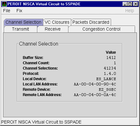
The following table describes the data displayed:
| Data | Description |
|---|---|
| Buffer Size | Maximum data buffer size for this virtual circuit. |
| Channel Count | Number of channels available for use by this virtual circuit. |
| Channel Selections | Number of channel selections performed. |
| Protocol | NISCA protocol version. |
| Local Device | Name of the local LAN device that the channel uses to send and receive packets. |
| Local LAN Address | Address of the local LAN device that performs sends and receives. |
| Remote Device | Name of the remote LAN device that the channel uses to send and receive packets. |
| Remote LAN Address | Address of the remote LAN device performing the sends and receives. |
VC closures data is information about the number of times a virtual circuit has closed for a particular reason. Figure 3-22 is an example of a VC Closures Data page.
Figure 3-22 Virtual Connect (VC) Closures Data Page
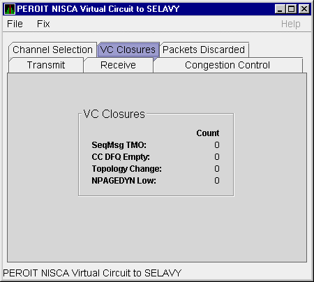
The following table describes the displayed data:
| Data | Description |
|---|---|
| SeqMsg TMO | Number of times the VC was closed because of sequenced transmit timeouts. |
| CC DFQ Empty | Number of times the VC was closed because the channel control data-free queue (DFQ) was empty. |
| Topology Change | Number of times the VC was closed because PEDRIVER performed a failover from a LAN path with a large packet size to a LAN path with a smaller packet size, necessitating the closing and reopening of the virtual circuit. |
| NPAGEDYN Low | Number of times the virtual circuit was lost because of a pool allocation failure on the local node. |
Packets discarded data is information about the number of times packets were discarded for a particular reason. Figure 3-23 is an example of a Packets Discarded Data page.
Figure 3-23 Packets Discarded Data Page
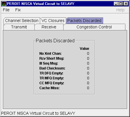
The following table describes the displayed data:
| Data | Description |
|---|---|
| No Xmt Chan | Number of times there was no transmit channel. |
| Rcv Short Msg | Number of times an undersized transport message was received. |
| Ill Seq Msg | Number of times an illegal sequenced message was received. |
| Bad Checksum | Number of times there was a checksum failure on a received packet. |
| TR DFQ Empty | Number of times the transmit data-free queue (DFQ) was empty. |
| TR MFQ Empty | Number of times the transmit message-free queue (MFQ) was empty. |
| CC MFQ Empty | Number of times the channel control MFQ was empty. |
| Cache Miss | Number of packets that could not be placed in the virtual circuit's receive cache because the cache was full. |
Transmit data is information about data packet transmission. Figure 3-24 is an example of a Transmit Data page.
Figure 3-24 Transmit Data Page
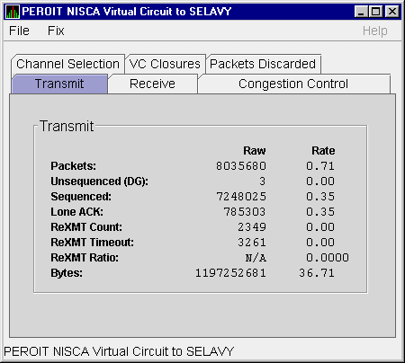
The following table describes the displayed data:
| Data | Description |
|---|---|
| Packets | (Raw) count and rate of packets transmitted through the virtual circuit to the remote node, including both sequenced and unsequenced (channel control) messages and lone acknowledgments. |
| Unsequenced (DG) | (Raw) count and rate of the number of unsequenced packets transmitted. |
| Sequenced | (Raw) count and rate of sequenced packets transmitted. Sequenced packets are guaranteed to be delivered. |
| Lone ACK | (Raw) count and rate of packets sent solely for the purpose of acknowledging receipt of one or more packets. |
| ReXMT Count | Number of packets retransmitted. Retransmission occurs when the local node does not receive an acknowledgment for a transmitted packet within a predetermined timeout interval. |
| ReXMT Timeout | Number of retransmission timeouts that have occurred. |
| ReXMT Ratio | Ratio of current and past retransmission count to the current and past number of sequenced messages sent. |
| Bytes | (Raw) count and rate of bytes transmitted through the virtual circuit. |
| Previous | Next | Contents | Index |
![[Go to the documentation home page]](../../images/buttons/bn_site_home.gif)
![[How to order documentation]](../../images/buttons/bn_order_docs.gif)
![[Help on this site]](../../images/buttons/bn_site_help.gif)
![[How to contact us]](../../images/buttons/bn_comments.gif)
|
| privacy and legal statement | ||
| 6552PRO_004.HTML | ||