![[Compaq]](../../images/compaq.gif)
![[Go to the documentation home page]](../../images/buttons/bn_site_home.gif)
![[How to order documentation]](../../images/buttons/bn_order_docs.gif)
![[Help on this site]](../../images/buttons/bn_site_help.gif)
![[How to contact us]](../../images/buttons/bn_comments.gif)
![[OpenVMS documentation]](../../images/ovmsdoc_sec_head.gif)
| Document revision date: 30 March 2001 | |
|
|
|
|
|
|
| Previous | Contents | Index |
Receive data is information about the receipt of data packets. Figure 3-25 is an example of a Receive Data page.
Figure 3-25 Receive Data Page
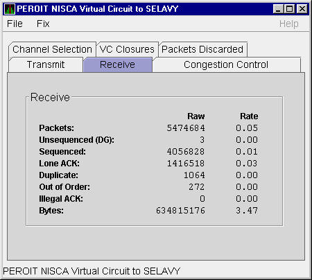
The following table describes the displayed data:
| Data | Description |
|---|---|
| Packets | (Raw) count and rate of packets received on the virtual circuit from the remote node, including both sequenced and unsequenced (channel control) messages and lone acknowledgments. |
| Unsequenced (DG) | (Raw) count and rate of unsequenced packets received. |
| Sequenced | (Raw) count and rate of sequenced packets received. |
| Lone ACK | (Raw) count and rate of lone acknowledgments received. |
| Duplicate | Number of redundant packets received by this system. Duplicates occur when the sending node retransmits a packet and both the original and retransmitted packets are received. |
| Out of Order | Number of packets received out of order by this system. |
| Illegal ACK | Number of illegal acknowledgments received. |
| Bytes | (Raw) count and rate of bytes received through the virtual circuit. |
Congestion control data is information about transmit congestion. The values indicate the number of messages that can be sent to the remote node before receiving an acknowledgment and the retransmission timeout.
Figure 3-26 is an example of a Congestion Control Data page.
Figure 3-26 Congestion Control Data Page
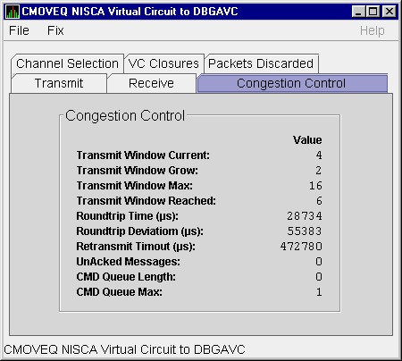
The following table describes the displayed data:
When you double-click a PID on the lower part of an OpenVMS CPU Process (Figure 3-7), Memory (Figure 3-9), or I/O (Figure 3-10) page, the Availability Manager displays the first of several OpenVMS Single Process pages. These pages allow you to click tabs to display specific data about one process.
The following pages display data about a single process and are described in subsequent sections:
When you click the Process Information tab, the Availability Manager displays the OpenVMS Process Information page, as shown in Figure 3-27. The data on this page is displayed at the default intervals shown for Single Process Data on the Data Collection customizations.
Figure 3-27 Process Information Page
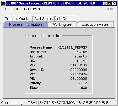
The following table describes the data on this page:
| Data | Description |
|---|---|
| Process name | Name of the process. |
| Username | User name of the user who owns the process. |
| Account | Account string that the system manager assigns to the user. |
| UIC | User identification code (UIC). A pair of numbers or character strings that designate the group and user. |
| PID | Process identifier. A 32-bit value that uniquely identifies a process. |
| Owner ID | Process identifier of the process that created the process displayed on the page. If the PID is 0, then the process is a parent process. |
| PC |
Program counter.
On OpenVMS Alpha systems, this value is displayed as 0 because the data is not readily available to the Data Collector node. |
| PSL | Processor status longword (PSL). This value is displayed on VAX systems only. |
| Priority | Computable and base priority of the process. Priority is an integer between 0 and 31. Processes with higher priority are given more CPU time. |
| State | One of the process states listed in Appendix A. |
When you click the Working Set tab, the Availability Manager displays the OpenVMS Working Set page (Figure 3-28).
Figure 3-28 Working Set Page
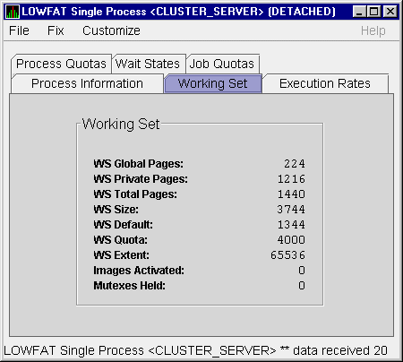
The following table describes the data on this page:
| Data | Description |
|---|---|
| WS Global Pages | Shared data or code between processes, listed in pages (measured in pagelets). |
| WS Private Pages | Amount of accessible memory, listed in pages (measured in pagelets). |
| WS Total Pages | Sum of global and private pages (measured in pagelets). |
| WS Size | Working set size. The number of pages (measured in pagelets) of memory the process is allowed to use. This value is periodically adjusted by the operating system based on analysis of page faults relative to CPU time used. Increases in large units indicates that a process is taking many page faults, and its memory allocation is increasing. |
| WS Default | Working set default. The initial limit of the number of physical pages (measured in pagelets) of memory the process can use. This parameter is listed in the user authorization file (UAF); discrepancies between the UAF value and the displayed value are due to page/longword boundary rounding or other adjustments made by the operating system. |
| WS Quota | Working set quota. The maximum amount of physical pages (measured in pagelets) of memory the process can lock into its working set. This parameter is listed in the UAF; discrepancies between the UAF value and the displayed value are due to page/longword boundary rounding or other adjustments made by the operating system. |
| WS Extent | Working set extent. The maximum number of physical pages (measured in pagelets) of memory the system will allocate for the process. The system provides memory to a process beyond its quota only when it has an excess of free pages and can be recalled if necessary. This parameter is listed in the UAF; any discrepancies between the UAF value and the displayed value are due to page/longword boundary rounding or other adjustments made by the operating system. |
| Images Activated | Number of times an image is activated. |
| Mutexes Held | Number of mutual exclusions (mutexes) held. Persistent values other than zero (0) require analysis. A mutex is similar to a lock but is restricted to one CPU. When a process holds a mutex, its priority is temporarily increased to 16. |
When you click the Execution Rates tab, the Availability Manager displays the OpenVMS Execution Rates page, as shown in Figure 3-29.
Figure 3-29 Execution Rates Page
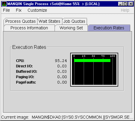
The following table describes the data on this page:
| Data | Description |
|---|---|
| CPU | Percent of CPU time used by this process. The ratio of CPU time to elapsed time. |
| Direct I/O | Rate at which I/O transfers take place from the pages or pagelets containing the process buffer that the system locks in physical memory to the system devices. |
| Buffered I/O | Rate at which I/O transfers take place for the process buffer from an intermediate buffer from the system buffer pool. |
| Paging I/O | Rate of read attempts necessary to satisfy page faults. This is also known as page read I/O or the hard fault rate. |
| Page Faults | Page faults per second for the process. |
When you click Process Quotas, the Availability Manager displays the OpenVMS Process Quotas page, as shown in Figure 3-30.
Figure 3-30 Process Quotas Page
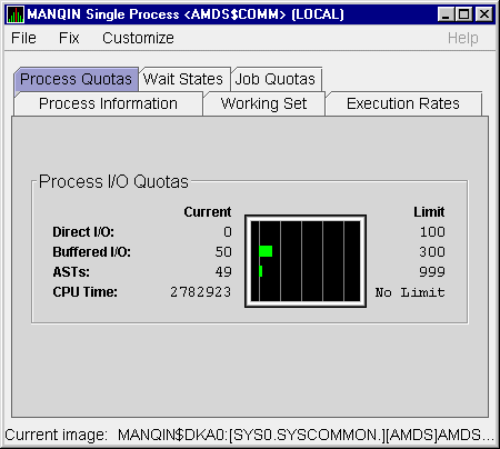
The following table describes the data on this page. Note that when you display the SWAPPER process, no values are listed in this section. The SWAPPER process does not have quotas defined in the same way as other system and user processes do.
| Data | Description |
|---|---|
| Direct I/O | The current number of direct I/Os used compared with the limit possible. |
| Buffered I/O | The current number of buffered I/Os used compared with the possible limit. |
| ASTs | Asynchronous system traps. The current number of ASTs used compared with the possible limit. |
| CPU Time | Amount of time used compared with the possible limit (in ms). "No Limit" is displayed if the limit is 0. |
When you click the Wait States tab, the Availability Manager displays the OpenVMS Wait States page, as shown in Figure 3-31.
Figure 3-31 Wait States Page
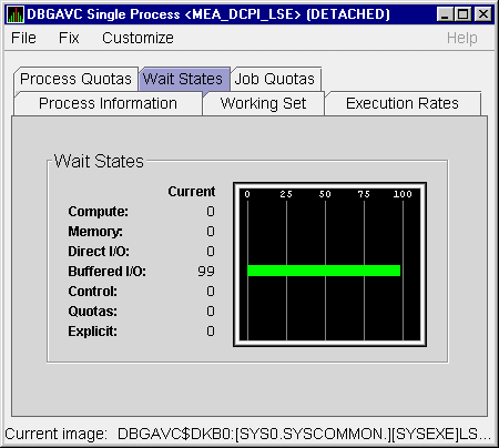
The following table describes the data on this page. The wait state specifies why a process cannot execute, based on calculations made on collected data. Each value is calculated over a data collection period of approximately 2 minutes.
"Current" refers to the percentage of elapsed time each process spends in one of the computed wait states. If a process spends all its time waiting in one state, the total approaches 100%.
Appendix A contains descriptions of process wait states.
| Data | Description |
|---|---|
| Compute | Relative value indicating that the process is waiting for CPU time. Possible states are COM, COMO, or RWCAP. |
| Memory | Relative value indicating that the process is waiting for a page fault that requires data to be read from disk; this is common during image activation. Possible states are PFW, COLPG, FPG, RWPAG, RWNPG, RWMPE, or RWMPB. |
| Direct I/O | Relative value indicating that the process is waiting for data to be read from or written to a disk. The possible state is DIO. |
| Buffered I/O | Relative value indicating that the process is waiting for data to be read from or written to a slower device such as a terminal, line printer, or mailbox. The possible state is BIO. |
| Control | Relative value indicating that the process is waiting for another process to release control of some resource. Possible states are CEF, MWAIT, LEF, LEFO, RWAST, RWMBX, RWSCS, RWCLU, RWCSV, RWUNK, or LEF waiting for an ENQ. |
| Quotas | Relative value indicating that the process is waiting because the process has exceeded some quota. Possible states are QUOTA or RWAST_QUOTA. |
| Explicit | Relative value indicating that the process is waiting because the process asked to wait, such as a hibernate system service. Possible states are HIB, HIBO, SUSP, SUSPO, or LEF waiting for a TQE. |
When you click the Job Quotas tab, the Availability Manager displays the OpenVMS Job Quotas page, as shown in Figure 3-32.
Figure 3-32 Job Quotas Page
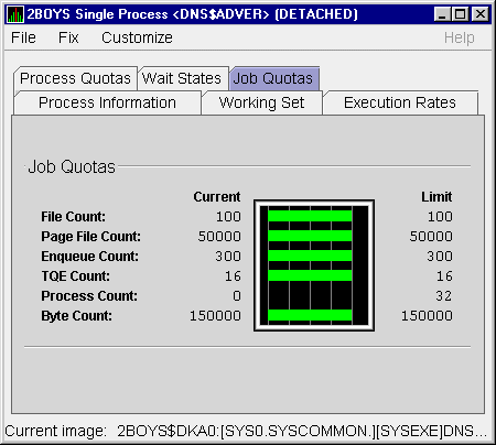
The following table describes the data on this page:
| Data | Description |
|---|---|
| File Count | Current number of open files compared with the possible limit. |
| Page File Count | Current number of disk blocks in the page file that the process can use compared with the possible limit. |
| Enqueue Count | Current number of resources (lock blocks) queued compared with the possible limit. |
| TQE Count | Current number of timer queue entry (TQE) requests compared with the possible limit. |
| Process Count | Current number of subprocesses created compared with the possible limit. |
| Byte Count | Current number of bytes used for buffered I/O transfers compared with the possible limit. |
Before you start this chapter, be sure to read the explanation of data collection, events, thresholds, and occurrences in Chapter 1. |
The Availability Manager indicates resource availability problems in the Events pane of the main Application window (Figure 4-1).
Figure 4-1 Application Window
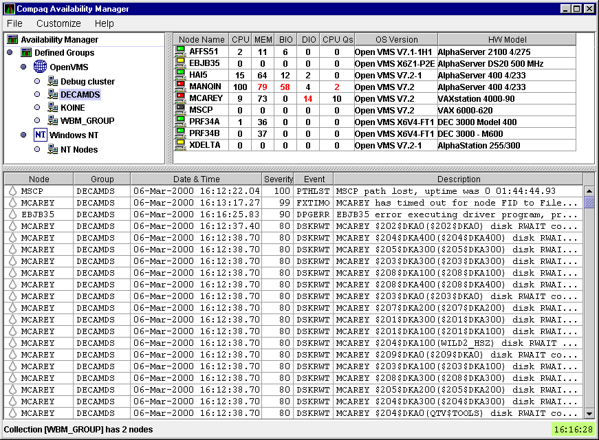
The Events pane, which occupies the lower section of the window, allows
you to identify a system problem. In many cases, you can apply fixes to
correct these problems as well (see Chapter 5). The Availability Manager
displays a warning message in the Events pane whenever it detects a
resource availability problem.
4.1 Displaying Event Information
The Availability Manager automatically displays events for all nodes currently in communication with the Data Analyzer. When an event of a specific severity occurs, the Availability Manager adds the event to a list in the Events pane.
By default, the Events pane displays more serious events in red and less serious events in yellow; more serious events are listed first.
The length of time an event is displayed depends on the severity of the
event. Less severe events are displayed for a short period of time (30
seconds); more severe events are displayed until you explicitly remove
the event from the Events pane (explained in Section 4.1.2).
4.1.1 Data in the Events Pane
Table 4-1 identifies the data items displayed in the Events pane.
| Data Item | Description |
|---|---|
| Node | Name of the node causing the event |
| Group | Group of the node causing the event |
| Date | Date the event occurred |
| Time | Time that an event was detected |
| Sev | Severity: a value from 0 to 100 |
| Event | Alphanumeric identifier of the type of event |
| Description | Short description of the resource availability problem |
Appendix B contains tables of events that are displayed in the Event
pane. In addition, these tables contain an explanation of each event
and the recommended remedial action.
4.1.2 Events Pane Menu Options
When you right-click a node name or data item in the Events pane, the Availability Manager displays a popup menu with the following options:
| Menu Option | Description |
|---|---|
| Display | Displays the Node Summary page associated with that event. |
| Fix | Displays a list of fix options (see Chapter 5.) |
| Remove | Removes an event from the display. |
| Freeze/Unfreeze | Freezes a value in the display until you "unfreeze" it; a snowflake icon is displayed to the left of an event that is frozen. |
| Customize | Allows you to customize events. |
The Availability Manager uses the following criteria to determine whether to signal an event and display it in the Events pane:
Figure 4-2 Sample Event Customization Page
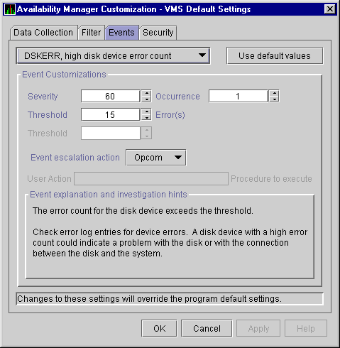
Figure 4-3 OpenVMS Data Collection Page
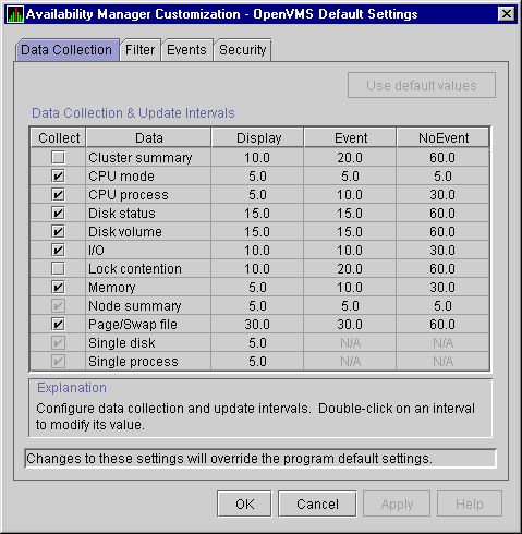
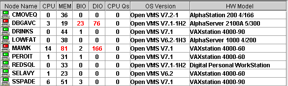
Figure 4-4 OpenVMS Node Pane
AMDS$AM_LOG:AVAILMANEVENTS.LOG
|
EVENTS.LOG
|
VAXJET 01-22-1999 11:24:50.67 0 CFGDON VAXJET configuration done DBGAVC 01-22-1999 11:25:12.41 0 CFGDON DBGAVC configuration done AFFS5 01-22-1999 11:25:13.23 0 CFGDON AFFS5 configuration done DBGAVC 01-22-1999 11:25:18.31 80 LCKCNT DBGAVC possible contention for resource REG$MASTER_LOCK VAXJET 01-22-1999 11:25:27.47 40 LOBIOQ VAXJET LES$ACP_V30 has used most of its BIOLM process quota PEROIT 01-22-1999 11:25:27.16 0 CFGDON PEROIT configuration done KOINE 01-22-1999 11:25:33.05 99 NOSWFL KOINE has no swap file MAWK 01-22-1999 11:26:20.15 99 FXTIMO MAWK Fix timeout for FID to Filename Fix MAWK 01-22-1999 11:26:24.48 60 HIDIOR MAWK direct I/O rate is high REDSQL 01-22-1999 11:26:30.61 10 PRPGFL REDSQL _FTA2: high page fault rate REDSQL 01-22-1999 11:26:31.18 60 PRPIOR REDSQL _FTA7: paging I/O rate is high MAWK 01-22-1999 11:26:24.48 60 HIDIOR MAWK direct I/O rate is high AFFS52 01-22-1999 11:25:33.64 60 DSKMNV AFFS52 $4$DUA320(OMTV4) disk mount verify in progress VAXJET 01-22-1999 11:38:46.23 90 DPGERR VAXJET error executing driver program, ... REDSQL 01-22-1999 11:39:18.73 60 PRCPWT REDSQL _FTA2: waiting in PWAIT REDSQL 01-22-1999 11:44:37.19 75 PRCCUR REDSQL _FTA7: has a high CPU rate |
| Previous | Next | Contents | Index |
|
|
| privacy and legal statement | ||
| 6552PRO_005.HTML | ||