![[OpenVMS documentation]](../../images/openvms_doc_banner_top.gif)
|
![[Site home]](../../images/buttons/bn_site_home_off.gif)
![[Send comments]](../../images/buttons/bn_comments_off.gif)
![[Help with this site]](../../images/buttons/bn_site_help_off.gif)
![[How to order documentation]](../../images/buttons/bn_order_docs_off.gif)
![[OpenVMS site]](../../images/buttons/bn_openvms_off.gif)
![[Compaq site]](../../images/buttons/bn_compaq_off.gif)
|
| Updated: 11 December 1998 |
VAX MACRO and Instruction Set Reference Manual
| Previous | Contents | Index |
The processor status longword (PSL) consists of a set of processor state variables associated with each process. Bits 31:16 of the PSL have privileged status. For information on this part of the PSL, refer to the VAX Architecture Reference Manual. Bits 15:0 of the PSL are referred to separately as the processor status word (PSW).
The format of the PSL is as follows:

The processor status word (PSW), bits 0 to 15 of the processor status longword, contains the following codes:
The condition codes are UNPREDICTABLE when they are affected by UNPREDICTABLE results. The VAX procedure call instructions conditionally set the IV and DV enable bits, clear the FU enable bit, and leave the T enable bit unchanged at procedure entry.
The PSL is saved automatically on the stack when an exception or interrupt occurs and is saved in the process control block on a process context switch. The PSL can also be read by the MOVPSL instruction.
The vector processor does not use PSL(IV) and PSL(FU) to enable integer
overflow and floating underflow exception checking for vector
instructions. Also, vector instruction exceptions do not affect the
values of the PSL condition codes bits.
8.4.1 C Bit
The C (carry) condition code bit, when set, indicates that the last
instruction that affected C had a carry out of the most-significant bit
of the result, or a borrow into the most-significant bit. When C is
clear, no carry or borrow occurred.
8.4.2 V Bit
The V (overflow) condition code bit, when set, indicates that the last
instruction that affected V produced a result whose magnitude was too
large to be properly represented in the operand that received the
result, or that there was a conversion error. When V is clear, no
overflow or conversion error occurred.
8.4.3 Z Bit
The Z (zero) condition code, when set, indicates that the last
instruction that affected Z produced a result that was zero. When Z is
clear, the result was nonzero.
8.4.4 N Bit
The N (negative) condition code bit, when set, indicates that the last
instruction that affected N produced a negative result. When N is
clear, the result was positive (or zero).
8.4.5 T Bit
The T (trace) bit, when set at the beginning of an instruction, causes
the TP bit in the Processor Status Longword to be set. When TP is set
at the end of an instruction, a trace fault is taken before the
execution of the next instruction. See Appendix E for additional
information on the TP bit and the trace fault.
8.4.6 IV Bit
The IV (integer overflow) bit, when set, forces an integer overflow
trap after execution of an instruction that produced an integer result
that overflowed or had a conversion error. When IV is clear, no integer
overflow trap occurs. (However, the condition code V bit is still set.)
8.4.7 FU Bit
The FU (floating underflow) bit, when set, forces a floating underflow
fault if the result of a floating-point instruction is too small in
magnitude to be represented in the result operand. When FU is clear, no
underflow fault occurs.
8.4.8 DV Bit
The DV (decimal overflow) bit, when set, forces a decimal overflow trap
after execution of an instruction that produced an overflowed decimal
(numeric string, or packed decimal) result or had a conversion error.
When DV is clear, no trap occurs. (However, the condition code V bit is
still set.)
8.5 Permanent Exception Enables
The processor action on certain exception conditions is not controlled
by bits in the PSW. Traps or faults always result from these exception
conditions.
8.5.1 Divide by Zero
A divide-by-zero trap is forced after the execution of an integer or
decimal division instruction that has a zero divisor. A fault occurs on
a floating-point division instruction that has a zero divisor.
8.5.2 Floating Overflow
A floating overflow fault is forced after the execution of a
floating-point instruction that produced a result too large to be
represented in the result operand.
8.6 Instruction and Addressing Mode Formats
The following sections describe the formats for instruction opcodes and
for the operand specifiers used with the various addressing modes.
8.6.1 Opcode Formats
An instruction is specified by the byte address A of its opcode.
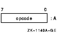
The opcode may extend over 2 bytes; the length depends on the contents of the byte at address A. If, and only if, the value of the byte is FC (hex) to FF (hex), the opcode is 2 bytes long.

Each instruction takes a specific sequence of operand specifier types. An operand specifier type conceptually has two attributes: the access type and the data type.
The access types include the following:
Access types 1 to 5 are general mode addressing. Type 6 is branch mode addressing.
The data types include the following:
For the address and branch access types, which do not directly reference operands, the data type indicates:
The following sections describe the operand specifier formats for the general addressing modes. For descriptions and examples of the use of the general addressing modes, see Chapter 5.
In Section 8.8, Table 8-5 is a summary of general register addressing and Table 8-6 is a summary of program counter addressing.
Notation for Describing Addressing Modes
The following notation describes the addressing modes:
| + | Addition |
| -- | Subtraction |
| * | Multiplication |
| <- | Is replaced by |
| = | Is defined as |
| ' | Concatenation |
| Rn or R[n] | The contents of register n |
| PC or SP | The contents of register 15 or 14, respectively |
| (x) | The contents of a location in memory whose address is x |
| { } | Arithmetic parentheses that indicate precedence |
| SEXT(x) | x is sign extended to size of operand needed |
| ZEXT(x) | x is zero extended to size of operand needed |
| OA | Operand address |
| ! | Comment delimiter |
In the formal descriptions of the addressing modes, the symbol for a register (for example, Rn or PC) always means the contents of the register (for example, the contents of register n or the contents of register 15). However, in text, when there is no ambiguity, the symbol for a register is often used as the name of a register (for example, Rn may be used for the name of register n, and PC may be used for the name of register 15). |
Each general mode addressing description includes the definition of the
operand address and the specified operand. For operand specifiers of
address access type, the operand address is the actual instruction
operand. For other access types, the specified operand is the
instruction operand. The branch mode addressing description includes
the definition of the branch address.
8.7.1 Register Mode
The operand specifier format is as follows:

No specifier extension follows.
In register mode addressing, the operand is the contents of either register n or (for quadword, D_floating, and certain field operands) register n+1 concatenated with register n.
| operand = | Rn | ! If 1 register |
| or | ||
| R[n+1]'Rn | ! If two registers | |
| or | ||
| R[n+3]'R[n+2]'R[n+1]'Rn | ! If four registers |
The assembler notation for register mode is Rn.
8.7.2 Register Deferred Mode
The operand specifier format is as follows:
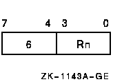
No specifier extension follows.
In register deferred mode addressing, the address of the operand is the contents of register n.
OA = Rn
operand = (OA)
The assembler notation for register deferred mode is (Rn).
8.7.3 Autoincrement Mode
The operand specifier format is as follows:

No specifier extension follows. If Rn denotes the PC, immediate data follows, and the mode is termed immediate mode.
In autoincrement mode addressing, the address of the operand is the contents of register n. After the operand address is determined, the size of the operand in bytes (1 for byte; 2 for word; 4 for longword and F_floating; 8 for quadword, G_floating, and D_floating; and 16 for octaword and H_floating) is added to the contents of register n, and the contents of register n are replaced by the result.
OA = Rn
Rn <- Rn + size
operand = (OA)
The assembler notation for autoincrement mode is (Rn)+. For immediate
mode, the notation is I^#constant, where constant is the immediate data
that follows.
8.7.4 Autoincrement Deferred Mode
The operand specifier format is as follows:

No specifier extension follows. If Rn denotes the PC, a longword address follows and the mode is termed absolute mode.
In autoincrement deferred mode addressing, the address of the operand is the contents of a longword whose address is the contents of register n. After the operand address is determined, 4 (the size in bytes of a longword address) is added to the contents of register n and the contents of register n are replaced by the result.
OA = (Rn)
Rn <- Rn + 4
operand = (OA)
The assembler notation for autoincrement deferred mode is @(Rn)+. For
absolute mode, the notation is @#address, where address is the longword
that follows.
8.7.5 Autodecrement Mode
The operand specifier format is as follows:

No specifier extension follows.
In autodecrement mode addressing, the size of the operand in bytes (1 for byte; 2 for word; 4 for longword and F_floating; 8 for quadword, G_floating, and D_floating; and 16 for octaword and H_floating) is subtracted from the contents of register n, and the contents of register n are replaced by the result. The updated contents of register n are the address of the operand.
Rn <- Rn - size
OA = Rn
operand = (OA)
The assembler notation for autodecrement mode is -(Rn).
8.7.6 Displacement Mode
There are three operand specifier formats.
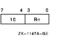
The specifier extension is a signed byte displacement that follows the operand specifier. This is the byte displacement mode.
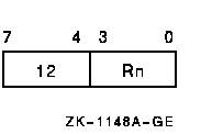
The specifier extension is a signed word displacement that follows the operand specifier. This is the word displacement mode.
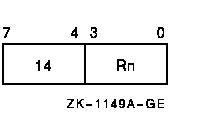
The specifier extension is a longword displacement that follows the operand specifier. This is the longword displacement mode.
In displacement mode addressing, the displacement (after it is sign extended to 32 bits, if it is byte or word displacement) is added to the contents of register n, and the result is the operand address.
OA = Rn + SEXT(displ) ! If byte or word displacement
or
Rn + displ ! If longword displacement
operand = (OA)
If Rn denotes PC, the updated contents of the PC are used. The address in the PC (the updated contents) is the address of the first byte beyond the specifier extension.
The assembler notation for byte, word, and long displacement mode is
B^D(Rn), W^D(Rn), and L^D(Rn), respectively, where D = displacement.
8.7.7 Displacement Deferred Mode
There are three operand specifier formats.
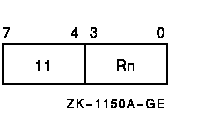
The specifier extension is a signed byte displacement that follows the operand specifier. This is the byte displacement deferred mode.

The specifier extension is a signed word displacement that follows the operand specifier. This is the word displacement deferred mode.
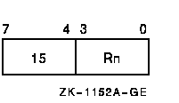
The specifier extension is a longword displacement that follows the operand specifier. This is the longword displacement deferred mode.
In displacement deferred mode addressing, the displacement (after it is sign extended to 32 bits, if it is byte or word displacement) is added to the contents of register n, and the result is the address of a longword whose contents are the operand address.
OA = (Rn + SEXT(displ)) ! If byte or word displacement
or
(Rn + displ) ! If longword displacement
operand = (OA)
If Rn denotes PC, the updated contents of the PC are used. The address in the PC (the updated contents) is the address of the first byte beyond the specifier extension.
The assembler notation for byte, word, and longword displacement
deferred mode is @B^D(Rn), @W^D(Rn), and @L^D(Rn), respectively, where
D = displacement.
8.7.8 Literal Mode
The operand specifier format is as follows:
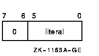
No specifier extension follows.
For operands of data type byte, word, longword, quadword, and octaword, the operand is the zero extension of the 6-bit literal field.
operand = ZEXT(literal) |
Thus, for these data types, you may use literal mode for values in the range 0 to 63.
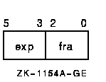
For operands of data type F_floating, G_floating, D_floating, and H_floating, the 6-bit literal field is composed of two, 3-bit fields. These fields are illustrated in the following diagram, where exp is exponent and fra is fraction:
You use the exponent and fraction fields to form an F_floating or D_floating operand as follows:
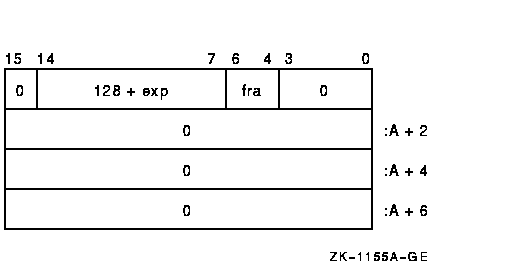
Note that bits 63:32 are not present in an F_floating operand.
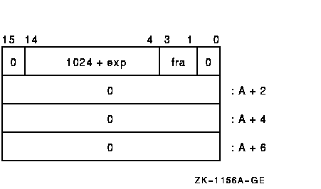
You use the exponent and fraction fields to form a G_floating operand as follows:
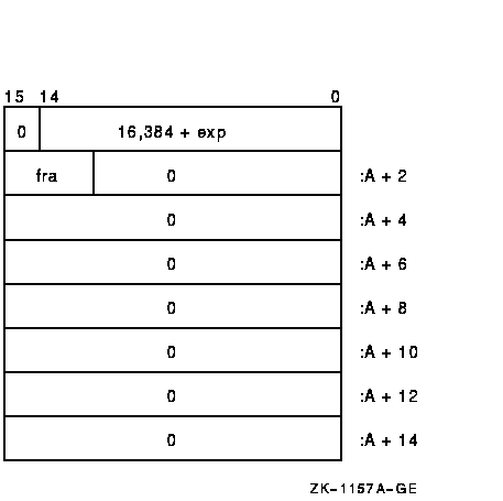
You use the exponent and fraction fields to form an H_floating operand as follows:
The range of values available is given in Table 8-3 and Table 8-4 in both decimal and rational number notation.
| Exponent | 0 | 1 | 2 | 3 | 4 | 5 | 6 | 7 |
|---|---|---|---|---|---|---|---|---|
| 0 | 0.5 | 0.5625 | 0.625 | 0.6875 | 0.75 | 0.8125 | 0.875 | 0.9375 |
| 1 | 1.0 | 1.125 | 1.25 | 1.37 | 1.5 | 1.625 | 1.75 | 1.875 |
| 2 | 2.0 | 2.25 | 2.5 | 2.75 | 3.0 | 3.25 | 3.5 | 3.75 |
| 3 | 4.0 | 4.5 | 5.0 | 5.5 | 6.0 | 6.5 | 7.0 | 7.5 |
| 4 | 8.0 | 9.0 | 10.0 | 11.0 | 12.0 | 13.0 | 14.0 | 15.0 |
| 5 | 16.0 | 18.0 | 20.0 | 22.0 | 24.0 | 26.0 | 28.0 | 30.0 |
| 6 | 32.0 | 36.0 | 40.0 | 44.0 | 48.0 | 52.0 | 56.0 | 60.0 |
| 7 | 64.0 | 72.0 | 80.0 | 88.0 | 96.0 | 104.0 | 112.0 | 120.0 |
| Exponent | 0 | 1 | 2 | 3 | 4 | 5 | 6 | 7 |
|---|---|---|---|---|---|---|---|---|
| 0 | 1/2 | 9/16 | 5/8 | 11/16 | 3/4 | 13/16 | 7/8 | 15/16 |
| 1 | 1 | 1-1/8 | 1-1/4 | 1-3/8 | 1-1/2 | 1-5/8 | 1-3/4 | 1-7/8 |
| 2 | 2 | 2-1/4 | 2-1/2 | 2-3/4 | 3 | 3-1/4 | 3-1/2 | 3-3/4 |
| 3 | 4 | 4-1/2 | 5 | 5-1/2 | 6 | 6-1/2 | 7 | 7-1/2 |
| 4 | 8 | 9 | 10 | 11 | 12 | 13 | 14 | 15 |
| 5 | 16 | 18 | 20 | 22 | 24 | 26 | 28 | 30 |
| 6 | 32 | 36 | 40 | 44 | 48 | 52 | 56 | 60 |
| 7 | 64 | 72 | 80 | 88 | 96 | 104 | 112 | 120 |
The assembler notation for literal mode is S^#literal.
| Previous | Next | Contents | Index |
![[Site home]](../../images/buttons/bn_site_home_off.gif)
![[Send comments]](../../images/buttons/bn_comments_off.gif)
![[Help with this site]](../../images/buttons/bn_site_help_off.gif)
![[How to order documentation]](../../images/buttons/bn_order_docs_off.gif)
![[OpenVMS site]](../../images/buttons/bn_openvms_off.gif)
![[Compaq site]](../../images/buttons/bn_compaq_off.gif)
|
![[OpenVMS documentation]](../../images/openvms_doc_banner_bottom.gif) |
|
Copyright © Compaq Computer Corporation 1998. All rights reserved. Legal |
4515PRO_014.HTML
|