![[OpenVMS documentation]](../../images/openvms_doc_banner_top.gif)
|
![[Site home]](../../images/buttons/bn_site_home_off.gif)
![[Send comments]](../../images/buttons/bn_comments_off.gif)
![[Help with this site]](../../images/buttons/bn_site_help_off.gif)
![[How to order documentation]](../../images/buttons/bn_order_docs_off.gif)
![[OpenVMS site]](../../images/buttons/bn_openvms_off.gif)
![[Compaq site]](../../images/buttons/bn_compaq_off.gif)
|
| Updated: 11 December 1998 |
|
|
|
|
| Updated: 11 December 1998 |
OpenVMS I/O User's Reference Manual
| Previous | Contents | Index |
A program can perform a movefile operation on a file if the following conditions are met:
The movefile operation moves a specified number of consecutive virtual blocks to new logical blocks on disk, beginning with the virtual block specified in the FIB$L_SVBN field.
The number of blocks moved is specified in the FIB$L_VBNCNT field. To move an entire file, specify FIB$L_VBNCNT as 0 and FIB$L_SVBN as 1.
To specify a starting logical block for the moved blocks, specify the logical block address in the FIB$L_LOC_ADDR subfield and set the FIB$C_LBN and the FIB$V_EXACT flags.
To move the blocks to another volume, or move blocks that span more than one volume, set the FIB$V_CHANGE_VOL flag of the FIB$L_ACCTL field. Use the FIB$B_LOC_RVN subfield of the FIB$W_ALLOC field to specify the volume to which the blocks are moved. If you do not specify a volume, the blocks are moved to the volume containing the first virtual block. Note that you cannot move blocks of a directory file to another volume.
If the file was previously marked as contiguous, the movefile operation sets the FIB$V_ALCON, FIB$V_ALCONB, and FIB$V_FILCON flags. This ensures that a contiguous file is not fragmented by a movefile operation.
For virtual blocks beyond the file's highwater mark, the movefile
operation allocates new logical blocks but does not copy the contents.
The position of the file's highwater mark remains unchanged.
1.6.7 Mount
On VAX and Alpha systems, mount is a virtual I/O function that informs the ACP when a disk or magnetic tape volume is mounted. MOUNT privilege is required.
IO$_MOUNT takes no arguments or function modifiers. This function is
part of the volume mounting operation only, and it is not meant for
general use. Most of the actual processing is performed by the MOUNT
command or the Mount Volume ($MOUNT) system service.
1.6.8 ACP Control
ACP Control is a virtual I/O function that performs miscellaneous control functions, depending on the arguments specified.
The following is the function code:
The following is the function modifier:
The following are the device- or function-dependent arguments for IO$_ACPCONTROL:
Table 1-14 lists FIB fields that control the processing of the IO$_ACPCONTROL function.
| Field | Subfields | Meaning |
|---|---|---|
| FIB$W_CNTRLFUNC | Specifies the control function to be performed. This field overlays FIB$W_EXCTL. | |
| FIB$L_CNTRLVAL 1 | Specifies additional function-dependent data. This field overlays FIB$L_EXSZ. | |
| FIB$L_ACL_STATUS | Status of the requested ACL attribute operation, if any. The ACL attributes are included in Table 1-7. If no ACL attributes are given, SS$_NORMAL is returned here. For Files-11 C/D, this field is always set to SS$_NORMAL. | |
| FIB$L_STATUS 1 | Alternate access status. The following bits are supported: | |
| FIB$V_ALT_REQ | Set to indicate whether the alternate access bit is required for the current operation. If not set, the alternate access bit is optional. | |
| FIB$V_ALT_GRANTED | If FIB$V_ALT_REQ = 0 and the alternate access check succeeded, the FIB bit returned from the file system is set. | |
| FIB$L_ALT_ACCESS 1 | A 32-bit mask that represents an access mask to check against file protection; for example, to open a file for read and to check whether it can be deleted or not. The mask has the same configuration as the standard protection mask. |
Table 1-15 the lists FIB field applicable to magnetic tape operations.
| Field | Subfields | Meaning |
|---|---|---|
| FIB$W_CNTRLFUNC | Several ACP control functions are used for magnetic tape positioning. These functions are specified by supplying a FIB with P1 containing the FIB descriptor address. Modifiers and parameters P2, P3, and P4 are not allowed. These functions clear serious exceptions in magnetic tape drivers. The following control functions can be specified to control magnetic tape positioning: | |
| FIB$C_REWINDFIL | Rewind to beginning-of-file. | |
| FIB$C_REWINDVOL | Rewind to beginning-of-volume set. | |
| FIB$C_POSEND | Position to end-of-volume set. | |
| FIB$C_NEXTVOL | Force next volume. | |
| FIB$C_SPACE | Space n blocks forward or backward. The FIB$L_CNTRLVAL field specifies the number of magnetic tape blocks to space forward if positive or to space backward if negative. | |
| FIB$C_CLSEREXCP | If set, clears the serious exception in the magnetic tape driver (see FIB$C_USEREOT in Section 1.6.1 and Section 1.6.2). If writing, allows you to write data blocks beyond the EOT marker, which can result in the magnetic tape not conforming to the ANSI standard for magnetic tapes (see ANSI Standard X3.27--1978). If reading, allows you to handle the move to the next volume or to stop reading the tape. Do not attempt to read past EOV. |
Several ACP control functions are available for disk volume control. The following function does not use parameters P2, P3, and P4:
The FIB$W_CNTRLFUNC field of the FIB specifies the following miscellaneous control functions (with no modifier on the IO$_ACPCONTROL function code). These functions use no other parameters.
| FIB$C_REMAP | Remap a file. The file window for the file open on the user's channel is remapped so that it maps the entire file. |
| FIB$C_LOCK_VOL |
Allocation lock the volume. Operations that change the file structure,
such as file creation, deletion, extension, and deaccess, are not
permitted. If such requests are queued to the file system for an
allocation-locked volume, they are not processed until the
FIB$C_UNLK_VOL function is issued to unlock the volume.
To issue the FIB$C_LOCK_VOL function, you must have either a system UIC or SYSPRV privilege, or be the owner of the volume. |
| FIB$C_UNLK_VOL | Unlock the volume. Cancels FIB$C_LOCK_VOL. To issue this function, you must have either a system UIC or SYSPRV privilege, or be the owner of the volume. |
Disk quota enforcement is enabled by a quota file on the volume, or relative volume 1 if the file is on a volume set. The quota file appears in the volume's master file directory (MFD) under the name QUOTA.SYS;1. This section describes the control functions that operate on the quota file.
Table 1-16 lists the enable and disable quota control functions.
| Value | Meaning |
|---|---|
| FIB$C_ENA_QUOTA |
Enable the disk quota file. If a nonzero directory file ID is specified
in FIB$W_DID, a lookup subfunction is performed to locate the quota
file (see Section 1.3.1). To issue this function, you must have either
a system UIC or SYSPRV privilege, or be the owner of the volume.
The quota file specified by FIB$W_FID, if present, is accessed by the ACP, and quota enforcement is turned on. By convention, the quota file is named [0,0]QUOTA.SYS;1. Therefore, FIB$W_DID should contain the value 4,4,0 and the name string specified with P2 should be "QUOTA.SYS;1". |
| FIB$C_DSA_QUOTA | Disable the disk quota file. The quota file is deaccessed and quota enforcement is turned off. To issue this function, you must have either a system UIC or SYSPRV privilege, or be the owner of the volume. |
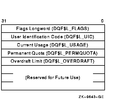
Table 1-17 lists the quota control functions that operate on individual entries in the quota file. Each operation transfers quota file data to and from the ACP using a quota data block. This block has the same format as a record in the quota file. Figure 1-9 shows the format of this block.
| Value | Meaning | ||||||
|---|---|---|---|---|---|---|---|
| FIB$C_ADD_QUOTA | Add an entry to the disk quota file, using the UIC and quota specified in the P2 argument block. FIB$C_ADD_QUOTA requires write access to the quota file. | ||||||
| FIB$C_EXA_QUOTA |
Examine a disk quota file entry. The entry whose UIC is specified in
the P2 argument block is returned in the P4 argument block, and its
length is returned in the P3 argument word. Using two flags in
FIB$L_CNTRLVAL, it is possible to search through the quota file using
wildcards. The two flags are:
The ACP maintains position context in FIB$L_WCC. On the first examine call, you specify 0 in FIB$L_WCC; the ACP returns a nonzero value so that each succeeding examine call returns the next matching entry. Read access to the quota file is required to examine all non-user entries. |
||||||
| FIB$C_MOD_QUOTA |
Modify a disk quota file entry. The quota file entry specified by the
UIC in the P2 argument block is modified according to the values in the
block, as controlled by three flags in FIB$L_CNTRLVAL.
The usage data can be changed only if the volume is locked by FIB$C_LOCK_VOL (see Section 1.6.8.3). FIB$C_MOD_QUOTA requires write access to the quota file. The P3 and P4 arguments return the modified quota entry to you. By using the flags FIB$V_ALL_MEM and FIB$V_ALL_GRP, you can search through the quota file using wildcards just as you would with the FIB$C_EXA_QUOTA function. |
||||||
| FIB$C_REM_QUOTA |
Remove a disk quota file entry whose UIC is specified in the P2
argument block. FIB$C_REM_QUOTA requires write access to the quota file.
The P3 and P4 arguments return the removed quota file entry to you. By using the flags FIB$V_ALL_MEM and FIB$V_ALL_GRP, you can search through the quota file using wildcards just as you would with the FIB$C_EXAQUOTA function. |
Figure 1-9 Quota File Transfer Block
IO$_ACPCONTROL functions that transfer quota file data between the caller and the ACP use the following device- or function-dependent arguments:
Figure 1-10 shows the I/O status block (IOSB) for ACP--QIO functions. Appendix A lists the status returns for these functions. (The OpenVMS system messages documentation provides explanations and suggested user actions for these returns.)
The file ACP returns a completion status in the first longword of the IOSB. In an extend operation, the second longword is used to return the number of blocks allocated to the file. If a contiguous extend operation (FIB$V_ALCON) fails, the second longword is used to return the size of the file after truncation.
Values returned in the IOSB are most useful during operations in compatibility mode. When executing programs in the native mode, use the values returned in FIB locations.
Figure 1-10 IOSB Contents---ACP-QIO Functions
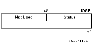
If an extend operation (including CREATE) was performed, IOSB+4 contains the number of blocks allocated, or the largest available contiguous space if a contiguous extend operation failed. If a truncate operation was performed, IOSB+4 contains the number of blocks added to the file size to reach the next cluster boundary.
This chapter describes the use of disk drivers that support the disk devices listed in the Software Product Description for the OpenVMS Operating System for Alpha and VAX. The chapter also includes descriptions of many of the supported disks and controllers. However, not all supported devices are described here. Refer to the Software Product Description for the OpenVMS Operating System for Alpha and VAX for the definitive list of supported devices.
All disk drivers support Files-11 On-Disk Structure Level 1 and Level 2
file structures. Access to these file structures is through the DCL
commands INITIALIZE and MOUNT, followed by the RMS calls described in
the OpenVMS Record Management Services Reference Manual. Files in RT-11 format can be read or written with
the file exchange facility EXCHANGE.
2.1 Supported Disk Devices and Controllers
The following sections provide descriptions of disk devices.
To obtain more information about a device, use the DCL command SHOW
DEVICE with the /FULL qualifier, the Get Device/Volume Information
($GETDVI) system service (from a program), or the F$GETDVI lexical
function (in a command line or command procedure). Section 2.3 lists
the information on disk devices returned by $GETDVI.
2.1.1 UDA50 UNIBUS Disk Adapter
The UDA50 UNIBUS Disk Adapter is a microprocessor-based disk controller for mass storage devices that implements the DIGITAL Storage Architecture (DSA); for more information on the DSA, see Section 2.2.3.
The UDA50 controller is used to connect any combination of four RA60, RA80, and RA81 disk drives to the UNIBUS. Two UDA50 controllers can be attached to a single UNIBUS for a maximum of eight disk drives per UNIBUS. On the VAX-11/780 processor, the operating system supports one UDA50 on the first UNIBUS, which can accommodate certain other options. Adding a second UDA50 requires a second UNIBUS. With the exception of the first UNIBUS, a maximum of two UDA50 controllers per UNIBUS are supported. If two UDA50 controllers are on a UNIBUS, no other options can be placed on that UNIBUS. The VAX-11/730 processor supports only one UDA50 per UNIBUS.
The UDA50, in implementing DSA, takes over the control of the physical disk unit. The operating system processes request virtual or logical I/O on disks controlled by the UDA50. The operating system maps virtual block addresses into logical block addresses. The UDA50 then resolves logical block addresses into physical block addresses on the disk.
The UDA50 controller corrects bad blocks on the disk by requesting that
the disk class driver revector a failing physical
block to another, error-free physical block on the disk; the logical
block number is not changed (see Section 2.2.11.1). Any bad blocks that
might exist on a disk attached to a UDA50 are transparent to the
operating system, which does logical or virtual I/O to such a disk. The
UDA50 also corrects most data errors.
2.1.2 KDA50 Disk Controller
The KDA50 disk controller is a two-module disk controller that allows
the RA-series DSA disk drives to be attached to Q-bus systems. The
KDA50 performs the same functions as the UDA50 (see Section 2.1.1).
2.1.3 KDB50 Disk Controller
The KDB50 disk controller is a two-module disk controller that allows
the RA-series DSA disk drives to be attached to BI bus systems, such as
the VAX 8200 processor. The KDB50 performs the same functions as the
UDA50 (see Section 2.1.1).
2.1.4 HSC40, HSC50, and HSC70 Controllers
HSC controllers are high-speed, high-availability controllers for mass storage devices that implement the DIGITAL Storage Architecture (DSA); for more information about the DSA, see Section 2.2.3. An HSC controller is connected to a processor by a CI bus (computer interconnect). The operating system supports the use of the HSC controllers in controlling the RA family of disks.
The HSC40 can support up to 12 SDI (standard disk interface) disks from the SA or RA families of disk drives or a combination of up to 12 SDI disk drives and TA-series tape drives.
The HSC70 can support up to 32 SDI disks from the SA or RA families of disk drives or a combination of SDI disk drives and TA-series tape drives.
HSC controllers, in implementing DSA, take over the control of the physical disk unit. System processes request virtual or logical I/O on disks controlled by the HSC controller. The operating system maps virtual block addresses into logical block addresses. The HSC controller then resolves logical block addresses into physical block addresses on the disk.
HSC controllers correct bad blocks on the disk by revectoring a failing physical block to another, error-free physical block on the disk; the logical block number is not changed. The operating system, which performs logical or virtual I/O to such a disk, does not recognize that any bad blocks might exist on a disk attached to an HSC controller. HSC controllers also correct most data errors.
The HSC series of controllers provides access to disks despite most hardware failures. Use of an HSC controller permits two or more processors to access files on the same disk.
Only one system should have write access to a Files-11 On-Disk Structure Level 1 disk or to a foreign-mounted disk; all other systems should only have read access to the disk. For Files-11 On-Disk Structure Level 2 volumes, the operating system enables read/write access to all nodes that are members of the same cluster. |
HSC-series controllers allow you to add or subtract disks from the
device configuration without rebooting the system.
2.1.5 SII Integral Adapter
The SII integral adapter on the MicroVAX 3300/3400 processor provides access through the DIGITAL Storage Systems Interconnect (DSSI) bus to a maximum of seven storage devices.
The term dual-host refers to pairs of CPUs connected to a bus. In dual-host configurations of MicroVAX 3300/3400 CPUs, the DSSI bus must be connected between the SII integral adapters present on both CPUs.
A maximum of six devices can be connected to the EDA640 adapter, which is implemeneted by the SII chip, DXX chip, and 128K RAM chip, in dual-host configurations.
| Previous | Next | Contents | Index |
|
|
![[OpenVMS documentation]](../../images/openvms_doc_banner_bottom.gif) |
|
Copyright © Compaq Computer Corporation 1998. All rights reserved. Legal |
6136PRO_004.HTML
|